Lesson 2 – DUT Board Design Considerations
535
Also, changes of the supply voltage will influence the generated or
received signal and thus increase the noise level.
Use lowpass filters or at least bypass capacitors to reduce noise.
• A lowpass filter can be directly inserted into the supply lines.
• Bypass capacitors should include electrolytic and ceramic capacitors.
Electrolytic capacitors (10 µF...100 µF) cover the low frequency
range.They can be positioned anywhere on the DUT board.
Ceramic capacitors (10 nF...100 nF) cover the high frequency range. They
should be placed as close to the DUT pins as possible.
At the very least, the following supplies should be filtered:
• Power supply for test circuit components
• Power supply for pull-up
• Power supply for relays
• DUT reference voltage
• Termination bias voltages
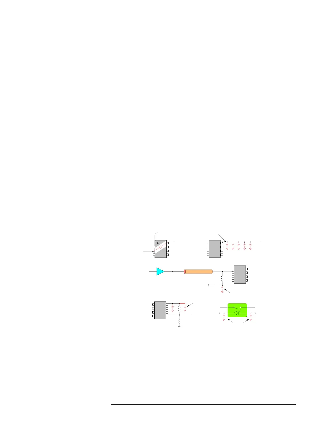
Some examples for bypass capacitor connections are shown in the figure
below:
Bypass Capacitors
VCC
GND
As short as possible
VCC
Use multiple bypass capacitors
ECL
Zo=50 ohm
50 ohm
- 2 V
Pin Driver
Digital
I/O Pin
VCC
Relay
Utility Line Utility Power
Supply

 Loading...


