Lesson 3 – Special Synchronization Options
544
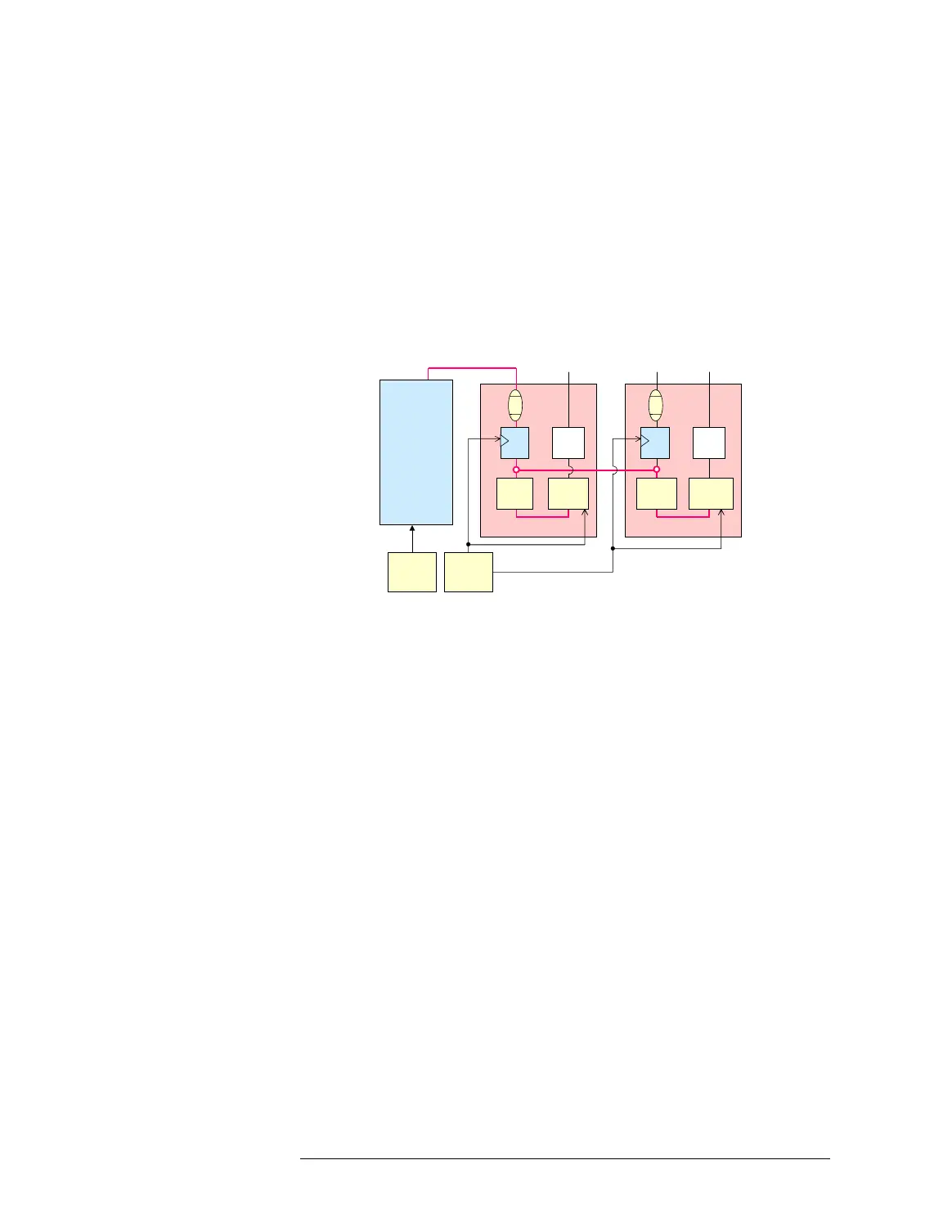
You can define any module in the loop of the “Master-Slave” internal
connection as master or slave. To define the slave module, use the ACMD
“SYNM” firmware command. If you define a module as a slave module,
the upstream module in the internal connection loop is defined as a master
module automatically. You can get the information about the “Master-
Slave” internal connection with the SOCB? firmware command.
The following figure is the block diagram for when the master/slave trigger
function is used:
Master/slave Trigger Function
For High Speed AWGs, 500M AWGs, and 1GHz Digitizers, the trigger-to-
signal delay for master and slave modules is always fixed and is the same
as when the master/slave trigger function is not used.
For Dual High Speed Samplers, 3GHz Samplers, or 100MHz Digitizer, the
trigger-to-signal delay for master and slave modules is different according
to the number of slave modules as follows:
For Dual High Speed Samplers:
Trigger-to-Signal Delay = 70 ns + (N x 15 ns)
where, N is the number of the slave modules for one master module.
For 3GHz Samplers:
Trigger-to-Signal Delay = 170 ns + (N x 15 ns)
where, N is the number of the slave modules for one master module.
For 100MHz digitizers:
Trigger-to-Signal Delay = 410 ns + 40 ns
This is fixed when the master/slave function is used for WDG, because
one master module of WDG can have only one slave module.
Digital Channel
Board
Master
Clock 1
Analog Module (Master)
Signal
pin
Digital Pin
Trigger
pin
Master
Clock 2
Analog Module (Slave)
Signal
pin
Trigger
pin
FF
Vernier
DAC
Timing
Generator
Timing
Generator
FF
Counter
Vernier
DAC
Counter
Master trigger
Master trigger

 Loading...


