Lesson 1 – Analog Modules
89
Sampling Technique
The following figure shows the undersampling technique of the
sampler:
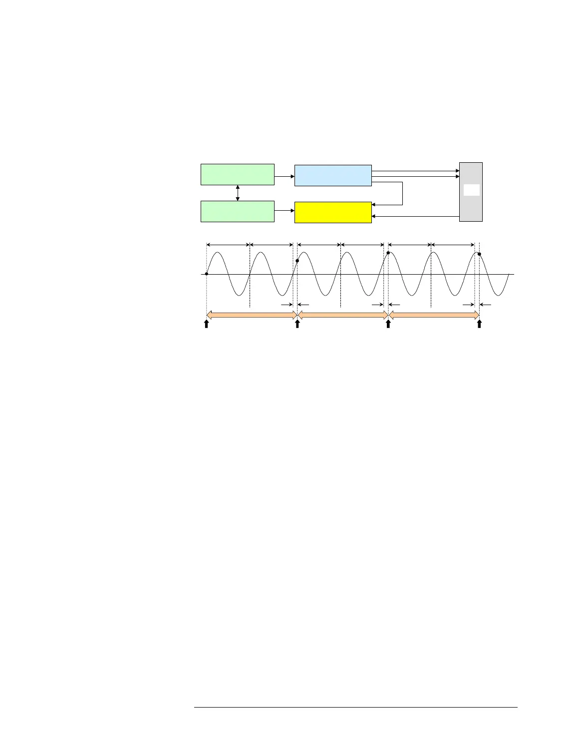
Measuring a Periodic Signal Using Undersampling
In the sampler, the sampling period (Ts) is slightly different (Ts_e)
from a multiple of the input signal period (Tin), that is
Ts = K × Tin + Ts_e. (Ts_e is called the equivalent sampling
period.)
To perform coherent sampling by using the undersampling
technique, the following equivalent sampling period requires for
the signal period:
Npoints × Ts_e = Mcycles_e × Tin
where Npoints is the number of sampled data points and
Mcycles_e is the number of captured signal cycles (not input
cycles). Npoints and Mcycles_e should be mutually prime, that is,
they have no common divisor other than 1.
NOTE To obtain a very short equivalent sampling period (Ts_e), the
sampling period (Ts) must be freely selectable. This can be achieved
by using a different master clock from the one for the signal to be
captured (the analog clock domain master clock and digital domain
master clock).
Phase Lock
DUT
Clock
Analog Out
Trigger
Master Clock
(Digital clock domain)
Master Clock
(Analog clock domain)
Digital I/O Channels
Sampler
Ts Ts Ts
Ts = K x Tin + Ts_e
Sample
Ts_e
Ts_e Ts_e
Tin
Tin
Tin
Tin
Tin
Tin
(K =2)
Data

 Loading...


