Omni Switch/Router Chassis and Power Supplies
Page 1-21
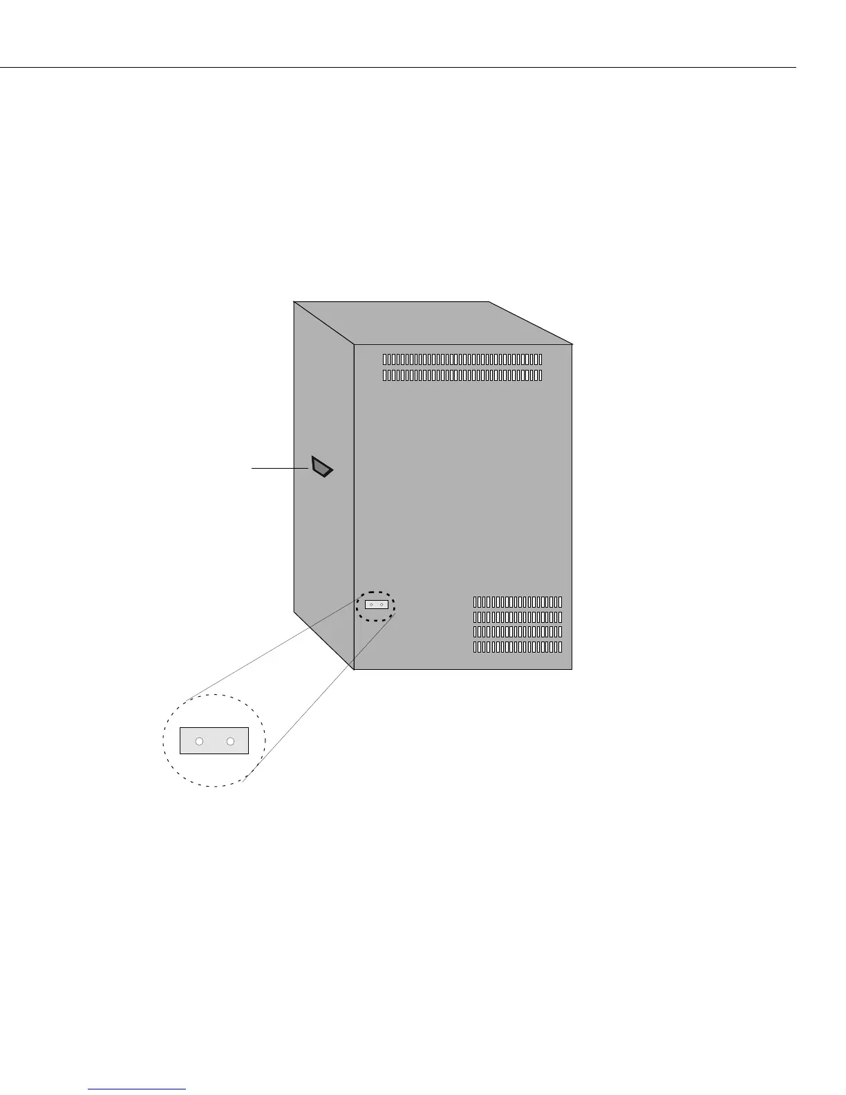
Grounding a Chassis
Omni Switch/Routers have two grounding screw holes on the back of the chassis. These
holes use 10-32 screws and are approximately 1 inch apart. In addition, these holes do not
have paint and are surrounded by a small paint-free rectangular section, which provides for a
good connection contact.
The figure below shows the location of the grounding screw holes on the back of an
OmniS/R-9. They are located approximately four (4) inches from the bottom of the chassis
and approximately one (1) inch from the left-hand side of the rear of the chassis.
Grounding Screw Holes on an OmniS/R-9
On an OmniS/R-5, the grounding screw holes are located approximately one (1) inch from
the bottom of the chassis and approximately one (1) inch from the left-hand side of the rear
of the chassis.
On an OmniS/R-3, they are located approximately four (4) inches from the bottom of the
chassis and approximately one (1) inch from the left-hand side of the rear of the chassis.
Lifting Handle
Grounding Screw Holes
 Loading...