Application Example 5
Page 24-10
Application Example 5
Traversing a Backbone
Application Example 5 illustrates why port-based policies may be required to establish
communications in some network situations, such as traversing a backbone. This necessity
arises because, as explained in How Routing Works Generally on page 24-8, AutoTracker does
not activate a VLAN – or its internal router interface – until a port is assigned to that VLAN.
AutoTracker assigns ports to VLANs with port policies immediately. However, AutoTracker
only assigns ports to VLANs with logical policies when a frame is received from a source
device that matches the VLAN’s policies. This means that, in some network situations, you
may need to assign a port policy to a VLAN to force it active.
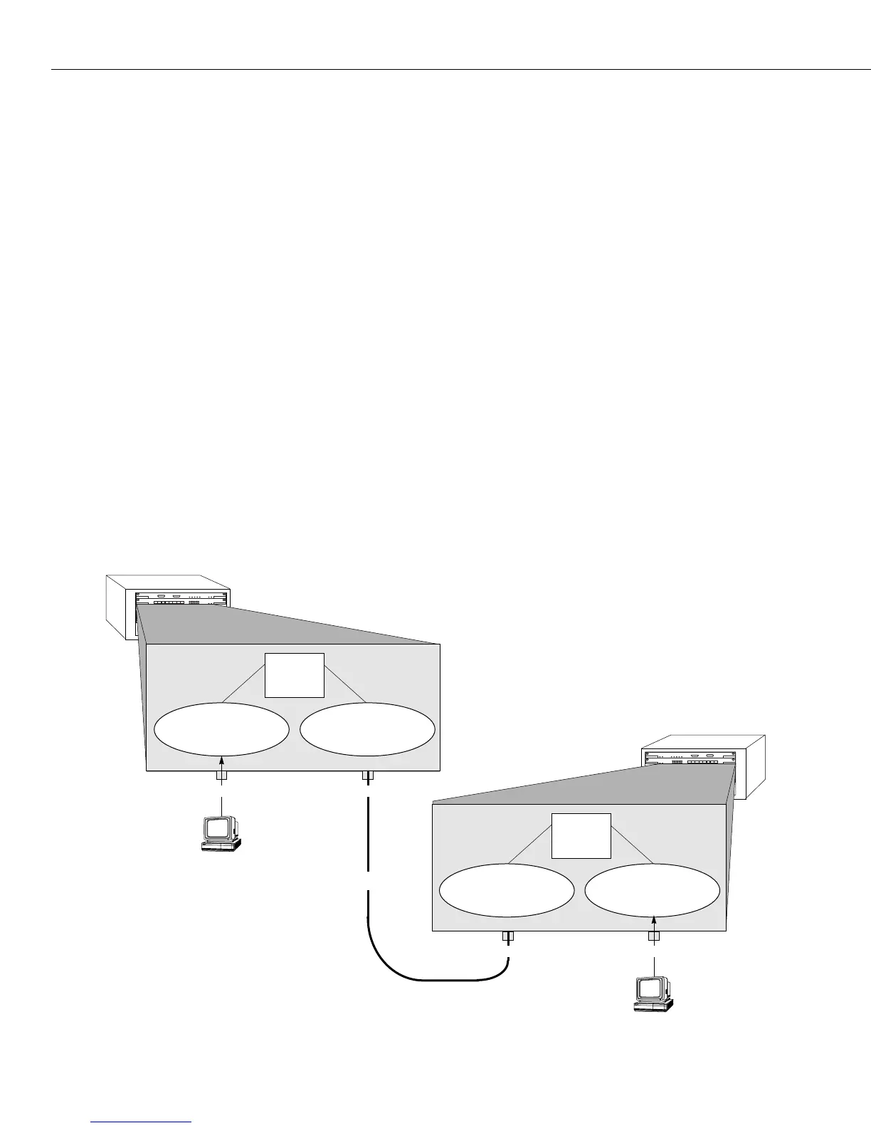
The figure below illustrates the problem that can occur. The network below contains two
Omni Switch/Routers in which three
IP network address VLANs exist: VLAN C (IP address
10.10.10.0), VLAN D (IP address 20.20.20.0), and VLAN E (IP address 30.30.30.0). VLAN D spans
both Omni Switch/Routers, but has no assigned devices. Routing is enabled for all three
VLANs. A backbone connects port 2 on Omni Switch/Router 1 to port 1 on Omni Switch/
Router 2.
When
IP workstation 10.10.10.1 transmits a frame VLAN C and its internal router activate.
When IP workstation 30.30.30.1 transmits a frame VLAN E and its internal router activate. All
subsequent traffic on VLAN C is transmitted to IP workstation 10.10.10.1 and all subsequent
traffic on VLAN E is transmitted to IP workstation 30.30.30.1. VLAN D cannot activate because
there are no devices that match its network address policy and it has no ports assigned.
Because VLAN D is not active, Switches 1 and 2 cannot exchange routing information. Switch
1 will not be aware of network 30 and Switch 2 will not be aware of network 10.
12345678
123456
12345678
123456
Omni Switch/Router 2
Omni Switch/Router 1
IP Workstation
10.10.10.1
Port 1 Port 2
Port 1
VLAN C
IP address 10.10.10.0
10.10.10.2
Internal
IP
Router
VLAN D
IP address 20.20.20.0
20.20.20.3
20.20.20.4
Internal
IP
Router
30.30.30.2
VLAN E
IP address 30.30.30.0
VLAN D
IP address 20.20.20.0
With this configuration,
VLAN D
can never become active because it
has neither assigned ports nor
attached devices. Thus, Switches 1
and 2 cannot share routing infor-
mation over the backbone.
Backbone
IP Workstation
30.30.30.1
Port 2
 Loading...