B13 BETTER (B13 BEST APPEARANCE) WASHING MACHINE SERVICE HANDBOOK
98
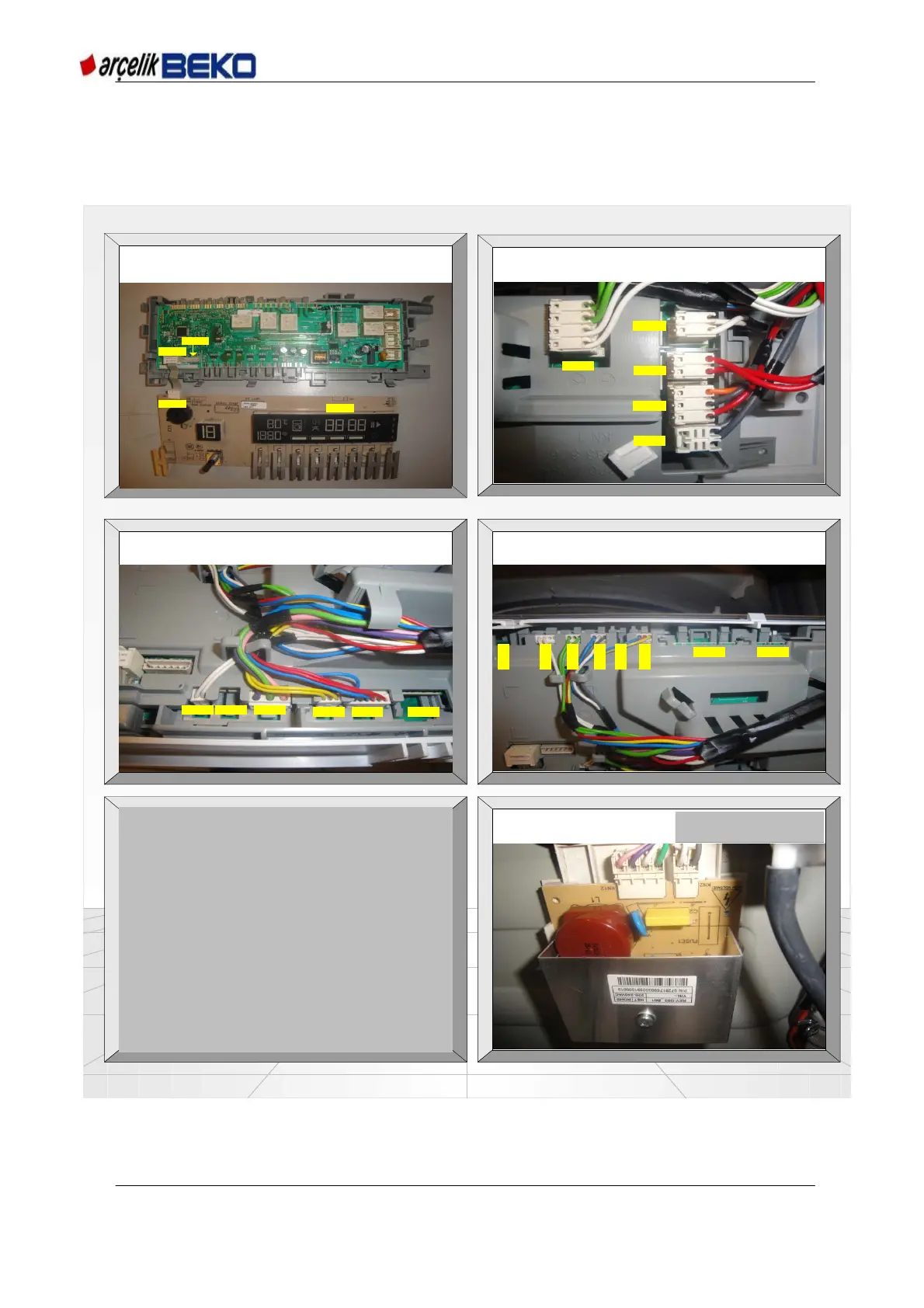
PICTURE-3 Control card socket
PICTURE-1 Control card and display card
PICTURE-4 Control card sockets
PICTURE-2 Control card sockets
KN25
KN11
KN2
KN1
KN08
KN03
KN23
KN05
KN24
KN17 KN14 KN12
KN16 KN13 KN22
KN21
KN09
KN20
KN19
KN18
KN04
KN07 KN06
PICTURE-5 Motor DC CARD sockets
KN2- UMDC MOTOR
THERMICKN12- U MDC
MOTOR COIL
KN1- DISPLAY CARD PROGRAMME INSTALLATION
KN2- DISPLAY CARD INPUT (DISPLAY)
KN03- 220 VAC INPUT
KN05- DOOR LOCK
KN06- MOTOR DC CARD (UMDC)
KN07- MO TOR (U MDC)
KN08- MOTOR-IMPEDANCE COIL (BLAC)
KN09- MOTOR COMMUNICATION (BLAC)
KN11- DISPLAY CARD INPUT (MAIN CARD)
KN12- DISCHARGE-JET PUMP
KN13- PREWASH-MAIN WASH VALVE
KN14- HOT WATER VALVE
KN16- STEAM VALVE
KN17- AQUASTOP
KN18- WATER LEVEL SENSOR
KN19- NTC
KN20- FLOWMETER (WATER COUNTER)
KN23- STEAM GENERATOR
KN24- HEATER
KN25- M AIN CARD PR OGR AM M E IN STA LLATION
12. FAILURE FLOW / TROUBLESHOOTING DIAGRAMS
12.1 Electronic Card Sockets