Do you have a question about the arcelik Beko B13 and is the answer not in the manual?
Includes general safety instructions for using the washing machine.
Details electrical safety precautions and connection requirements.
Defines the product details including manufacturer and model.
Provides the physical dimensions of the washing machine.
Lists general electrical and performance specifications.
Details the specifications of the washing machine motor.
Describes the components of the shock absorber system.
Guidance on selecting a suitable location for installing the machine.
Instructions for removing transport safety bolts before operation.
Details on how to connect the machine to the water supply.
Instructions for correctly connecting the drain hose.
Steps for safely connecting the washing machine to the electrical supply.
Steps to prepare laundry and the machine before washing.
Information on the maximum load capacity for different laundry types.
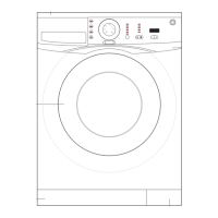
Overview and explanation of the washing machine's control panel.
Guide on how to select the appropriate wash programme.
Description of the primary wash programmes available.
Instructions on how to activate and deactivate the child lock feature.
Procedure for cleaning the detergent dispenser drawer.
Instructions for cleaning the door seal and the wash drum.
Steps for draining water and cleaning the pump filter.
Explains the water intake process and algorithm.
Describes the heating process and its control mechanism.
Details the structure and function of the electronic control board.
Explains the operation principle of the touch-sensitive controls.
Describes the steam generator and its operation principle.
Explains the function and operation of the water level sensor.
Details the specifications and types of the wash motor.
Explains the function of the door lock safety mechanism.
Describes the water heater component and its operation.
Details the drain pump's function and operational principle.
Procedure for entering the machine's service mode.
How to check and interpret error codes in service mode.
Procedure for displaying errors encountered during service mode.
Diagrams illustrating electronic card socket connections.
Troubleshooting guide for when the machine fails to operate.
Lists error codes and associated customer complaints.
Troubleshooting steps for Error Code E1.
Troubleshooting steps for Error Code E5.
Troubleshooting steps for issues related to the fuse blowing.
Lists specialized apparatus for shock absorber pin attachment.
Procedure for attaching and detaching the upper table assembly.
Instructions for attaching and detaching the front panel assembly.
Steps for removing and installing the front wall.
Procedures for attaching and detaching the steam generator and its parts.
Details on attachment and detachment of the washing machine motor.
Procedures for attaching and detaching shock absorbers and pins.
Instructions for removing and installing the drain pump.
Exploded view diagram of the drive system components.
Exploded view diagram of the control panel assembly.
Exploded view diagram of the washing machine's front door.
Exploded view diagram of the main body structure.
| Energy Efficiency Class | A+++ |
|---|---|
| Spin Speed | 1300 rpm |
| Number of Programs | 15 |
| Loading Type | Front loading |
| Maximum Spin Speed (RPM) | 1300 RPM |