Page 4–66
DURApulse GS4 AC Drive User Manual – 1st Ed, Rev A - 10/20/2017
Chapter 4: AC Drive Parameters
Type Hex Addr Dec Addr
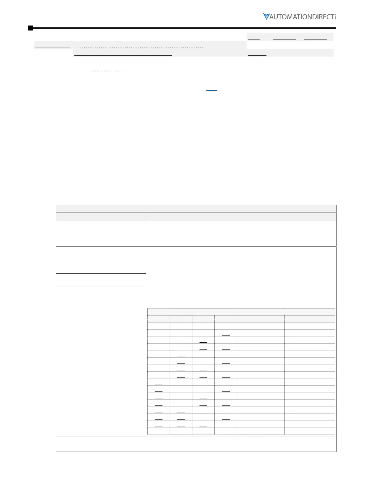
P3.03~P3.16 Multi-Function Input (MFI) Terminal Functions
R/W varies by parameter
Range/Units (Format: 16-bit unsigned) Default
0~50
(see P3�03~P3�16 Input Function Settings table below)
varies by parameter
These parameters set the functions of the Multi-Function Input terminals.
•
See Appendix C for Digital Input worksheet ( page C–3 )�
•
Terminals for parameters P3�11 to P3�16 are located on the optional extention cards, if installed�
If there is no expansion card installed, these parameters remain virtual terminals� For example,
after installing the multiple function expansion card “GS4-06CDD,” parameter P3�11 to P3�14 are
defined as corresponding parameters for terminals DI10 to DI13, but parameters P3�15 to P3�16
are still virtual terminals�
•
When terminals are defined as virtual, you need a digital keypad such as GS4-KPD or a
communication mode to modify status of bits 8~15 (0=ON, 1=OFF) at Parameter P3�42�
•
If an MFI will not take a setting, then most likely that setting is already assigned to a different
input� MFI inputs also cannot be changed when the drive is running�
•
When an external input is used in the GS4 PLC and the PLC is in Run or Stop mode, the PLC then
owns that input and any Multi-Function Input setting assigned via P3�03~P3�16 is void� To read
the status of an input into the PLC while maintaining the MFI setting, use the RPR command on
the DI Status Register (P3�46)� The ownership of the I/O can be returned to the drive by disabling
the PLC either through the keypad or digital inputs when they are assigned values 36 and 37�
Multi-Function Input Terminal Function Settings (P3.03~P3.16)
Setting: Function Function Description
0: No function
Setting a Multi-Function Input to 0 will disable that input� The purpose of this
function is to provide isolation for unused Multi-Function Input Terminals�
Any unused terminals should be programmed to 0 to make sure they have
no effect on drive operation.
1: Multi-Speed/PID Multi-Setpoint
bit 1
15 speeds can be commanded through the digital status of the 4 terminals; total
of 16 speeds if the master speed is included� (Refer to parameter group P5 for
settings�)
When settings 1, 2, & 3 are selected and registers P7�06~P7�12 are populated,
the Multi-Function Inputs refer to PID Multi-Setpoints� The SPs are determined
by P7�06~P7�12�
1) In order to use the Multi-PID SPs, P7.06~P7.12 must be set, and P7.00≠0.
2) When all PID Multi-Setpoint inputs are off, the GS4 drive reverts to the PID
Setpoint Source (P7�02)�
Multi-Speed / PID Setpoint Selection
Bit 4 Bit 3 Bit 2 Bit 1 Speed PID Setpoint
OFF OFF OFF OFF P4�00/P4�01 P7�02: SP Source
OFF OFF OFF ON P5�01: Speed 1 P7�06: Setpoint 1
OFF OFF ON OFF P5�02: Speed 2 P7�07: Setpoint 2
OFF OFF ON ON P5�03: Speed 3 P7�08: Setpoint 3
OFF ON OFF OFF P5�04: Speed 4 P7�09: Setpoint 4
OFF ON OFF ON P5�05: Speed 5 P7�10: Setpoint 5
OFF ON ON OFF P5�06: Speed 6 P7�11: Setpoint 6
OFF ON ON ON P5�07: Speed 7 P7�12: Setpoint 7
ON OFF OFF OFF P5�08: Speed 8 –
ON OFF OFF ON P5�09: Speed 9 –
ON OFF ON OFF P5�10: Speed 10 –
ON OFF ON ON P5�11: Speed 11 –
ON ON OFF OFF P5�12: Speed 12 –
ON ON OFF ON P5�13: Speed 13 –
ON ON ON OFF P5�14: Speed 14 –
ON ON ON ON P5�15: Speed 15 –
2: Multi-Speed/PID Multi-Setpoint
bit 2
3: Multi-Speed/PID Multi-Setpoint
bit 3
4: Multi-Speed bit 4
5: Reset After the error of the drive is eliminated, use this terminal to reset the drive�
(table continued next page)

 Loading...
