Appendix B: Optional I/O and Communication Cards
Page B–15
DuRApulse GS4 AC Drive User Manual – 1st Ed, Rev A - 10/20/2017
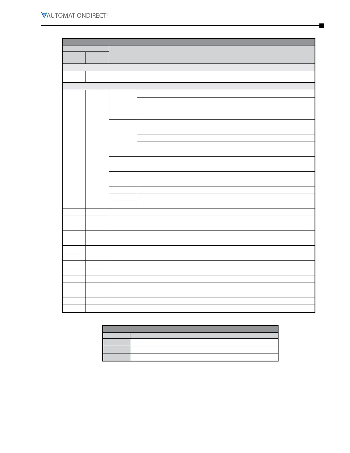
gs4-Cm-modTCp sTaTus Words
Communication Protocol Parameter Address Definitions
Address
DefinitionModbus
Decimal
Modbus
Hex
Status Monitor 1 – Warning Codes
48449 2100
Warning Code: Refer to Troubleshooting – Warning Codes in Chapter 6: Maintenance and
Troubleshooting
Status Monitor 2 – Status of GS4 AC Drive
48450 2101
bit 0~1
00: Stop
01: Decel during stop
10: Standby
11: Run
bit 2 1: JOG active
bit 3~4
00: Forward
01: Transition from Reverse to Forward
10: Transition from Forward to Reverse
11: Reverse
bit 5~7 Reserved
bit 8 1: Main Frequency comes from Communication Interface
bit 9 1: Main Frequency comes from Analog/External Terminal signal input
bit 10 1: The Command is operated by Communication Interface (keypad)
bit 11 1: Parameters have been Locked
bit 12 Running Status [0 = Drive Stopped; 1 = Drive Running (including Standby)]
bit 13~15 Reserved
48451 2102 Frequency Command (F) / PID Setpoint
48452 2103 Output Frequency (H)
48453 2104 Output Current (A)
48454 2105 DC Bus Voltage (U)
48455 2106 Output Voltage (E)
48456 2107 Multi Speed or PID Inputs current Step Number
48457 2108 Warning Codes
48458 2109 Digital Input Counter Value
48459 210A Power Factor Angle (cos Θ)
48460 210B reserved
48461 210C Actual Motor Speed (rpm)
48462 210D reserved
48463 210E reserved
48464 210F Power Output in kW
modbus CommuniCaTion
GS4-CM-MODTCP Modbus Function Codes
Code Definition
0x03
Read register in GS4
0x06
Write single register in GS4
0x10
Write multiple data registers in GS4

 Loading...
