Home
Automation Direct
Controller
DURApulse GS4
Page 67 (Main Terminal Diagrams)
Automation Direct DURApulse GS4 - Main Terminal Diagrams
542 pages
Manual
To Next Page
To Next Page
To Previous Page
To Previous Page
Loading...
Chapter 2: Inst
allation and Wiring
Page 2–29
DuRA
pulse
GS4
AC Drive User Manual – 1st Ed, Rev
A
- 10/20/2017
m
ain
T
erminal
d
iagrams
(
C
onTinued
)
f
rame
s
ize
d0, d m
ain
T
erminals
f
rame
s
ize
e–f m
ain
T
erminals
f
rame
s
ize
g m
ain
T
erminals
66
68
Table of Contents
Main Page
Blank
9
W Arnings and T Rademarks
3
Warning
3
Avertissement
4
Marques de Commerce
4
Warnings
5
Table of Contents
9
C Hapter 1: G Etting S Tarting
18
User Manual Overview
18
Overview of this Publication
18
Who Should Read this Manual
18
Supplemental Publications
18
Technical Support
18
Special Symbols
18
Purpose of AC Drives
19
Selecting the Proper Drive Rating
21
Dura Pulse
25
Storage and Transportation
25
Environmental Conditions
25
Dura Pulse GS4 AC Drive Specifications
26
Specifications Applicable to All GS4 Models
30
PID Control
30
Receiving and Inspection
31
Drive Package Contents
31
Unpacking Your GS4 Dura Pulse AC Drive
33
Lifting Eye Locations and Instructions
33
Unpacking the Drive
35
222 T C Able of
39
Chapter 2: Installation and Wiring
40
Drive Models by Frame Size
40
Installation
40
Minimum Clearances and Air Flow
41
Minimum Clearance Distances
41
Airflow and Power Dissipation
44
Dimensions
45
Circuit Connections - RFI Jumper
52
RFI Jumper Removal
52
Isolating Main Power from Ground
53
Floating Ground System (IT Systems)
54
Danger
55
Wiring Terminal Access
58
Control Terminal Access
58
Removing the Control Terminal Block
59
Main Circuit Wiring Terminals
60
Main Terminal Specifications
60
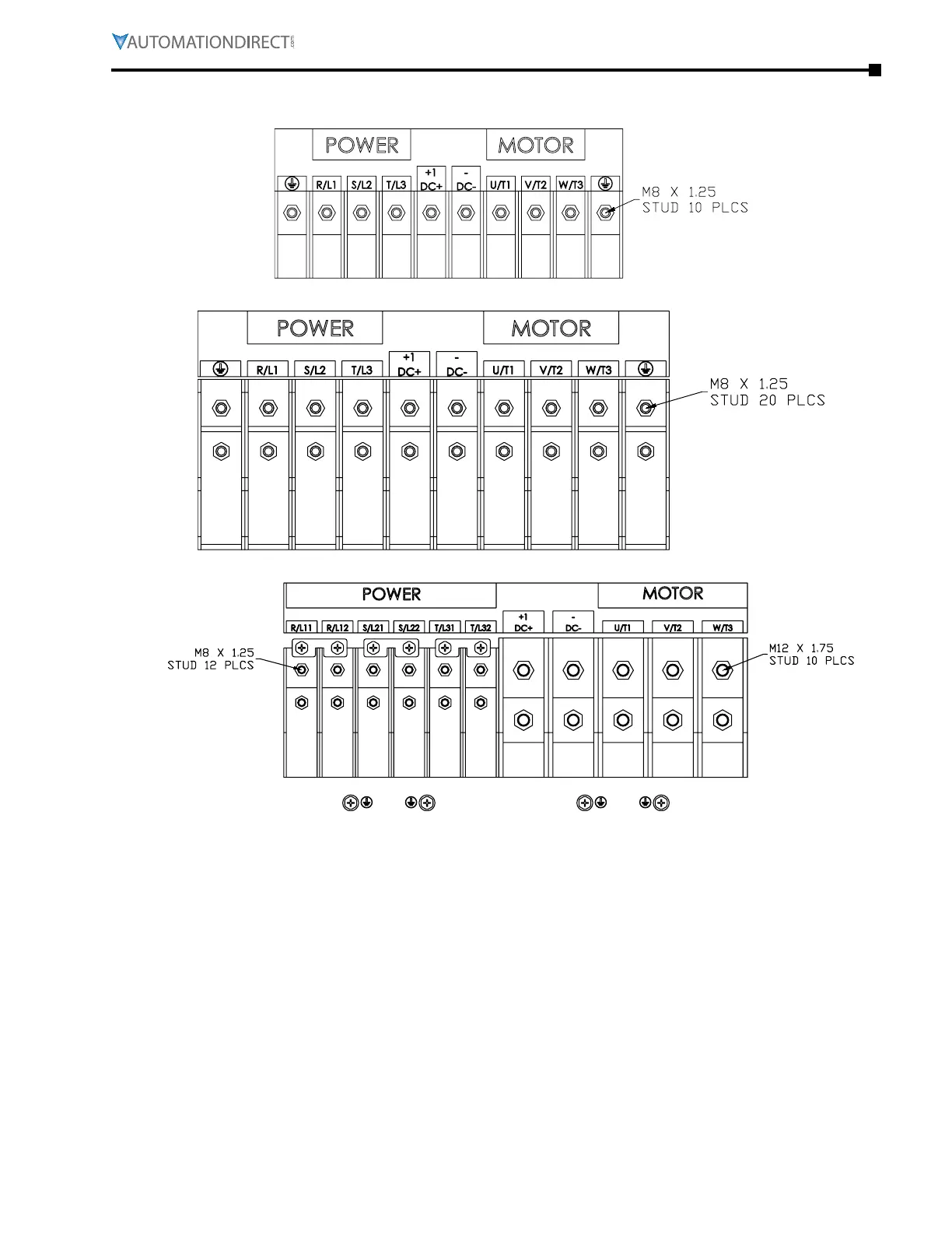
Main Terminal Diagrams
67
Main Circuit Wiring Diagrams
69
Control Circuit Wiring Terminals
70
Control Terminal Specifications
70
Control Circuit Wiring Terminals
71
Control Terminal Wiring Instructions
72
Control Circuit Wiring Diagrams
73
Digital Inputs
73
Chapter 3: Keypad Operation and Quick-Start
78
The Dura
78
GS4 Start-Up Display
80
Status Page
80
Menu Page
81
Param Setup - Parameter Setup Page
81
Quick-Start - Quick-Start Page
82
Keypad Lock - Keypad Lock Page
86
Fault Record - Fault Record Page
87
PLC - PLC Function Page
88
Copy Param - Copy Parameters Page (Keypad Copy)
89
Copy PLC - Copy PLC Page
90
Displ Setup - Display Setup Page
91
Time Setup - Time Setup Page
91
Language - Language Page
91
Start-Up - Start-Up Page
92
Keypad Fault Codes
93
Technical Support
93
Chapter 5 : Serial Communications. . . . . . . . . . . . . . . . . . . . . . . . . . . . 5-1
95
Communications Parameters Summary
95
Summary – Serial Communication Parameters
118
Serial Modbus Status Addresses
307
Serial Communication Parameters Summary (P9.XX)
308
Serial Communications Connectivity
315
Ccchapter Hapter Hapter 6 M T 6 6 Aintenance and Roubleshooting
333
Default Chapter
334
Annual Inspection
334
Maintenance and Inspections
334
Monthly Inspection
334
Recharge Capacitors (for Drives Not in Service)
335
Recommended Inspection Schedules
336
Recommended Inspection Schedules
337
Troubleshooting
338
Troubleshooting
340
Warning Codes
340
Fault Codes
348
Grease and Dirt Problems
358
Fiber Dust Problem
359
Corrosion Problem
360
Industrial Dust Problem
361
Digital Input/Output Terminal Problems
363
Chapter 6 : Maintenance and Troubleshooting . . . . . . . . . . . . . . . . . . . . . 6-1
365
Chapter 7 : Gsoft2 - G Etting Started. . . . . . . . . . . . . . . . . . . . . . . . . . . 7-1
365
GS4 Drive Configuration Software
365
Software Installation
369
Firmware Upgrade Notes
373
Ccchapter Hapter Hapter 8 Gsl I 8 8 Ogic Ntroduction
375
Introduction
375
For more Detailed Information
376
Gslogic Introduction
376
GS4 PLC Summary
377
Introduction
377
Connect to PLC
380
Getting Started
380
Installation of Gslogic Programming Software
383
System Requirements
383
About Getting Started
383
Software and Online Help Files
383
Technical Support
383
Program Writing
386
Basic Ladder Program Example
391
Program Download
393
Program Monitoring
394
GS4 Gslogic Program Examples
395
Aaappendix Ppendix Ppendix a a a a Ccessories
397
EMI Input Filters
398
EMI Filter Dimensions
399
EMI Filter Installation
401
Reflective Wave Phenomenon
402
Recommended Motor Cable Length
402
EMI Filter Installation
402
Fuses
405
Line/Load Reactors
406
DC Reactors (Choke) Specification Charts
408
Line/Load Reactor Specification Charts
409
Line Reactor Dimensions
410
Braking Units
419
Dynamic Braking
419
USB to RS-485 PC Adapter
420
USB-485M to GS4 Wiring and Pin-Out
420
Conduit Box Kit
421
Conduit Box Installation - Frame E
423
Conduit Box Installation - Frame F
424
Conduit Box Installation - Frame G
425
Flange Mounting Kits
427
Gs4-Kpd
435
Spare Keypad
435
Fan Removal
443
Fan Removal
444
Aaappendix Ppendix Ppendix O I\/O Ptional and B B B
451
Removing the Card Slot Cover
451
Installation
452
Removal
454
GS4-06CDD Combo I/O Card
455
Optional I/O Cards
455
GS4-06NA Input Card
457
GS4-06TR Output Card
457
Optional Communications Cards
458
GS4-CM-MODTCP Specifications
460
GS4-CM-MODTCP Control Words
464
GS4-CM-MODTCP Status Words
465
GS4-CM-ENETIP Specifications
466
GS4-CM-ENETIP Common Parameters
468
GS4-CM-ENETIP Ethernet/Ip I/O Messaging (Implicit Messaging
469
Data Format
472
Aaappendix Ppendix Ppendix D a I\/O Igital and Nalog C C C
479
GS4 Digital Inputs - Main Control Board
481
GS4 Digital Outputs - Main Control Board
482
GS4 Digital Inputs - Option Cards
483
GS4 Digital Outputs - Option Cards
484
GS4 Digital Outputs - Virtual
485
GS4 Analog Input 3 Parameters
488
GS4 Analog Output 1 Parameters
489
GS4 Analog Output 2 Parameters
489
GS4-CM-ENETIP Ethernet/Ip I/O Messaging (Implicit Messaging)
491
Appendix D Overview . . . . . . . . . . . . . . . . . . . . . . . . . . . . . . . . . . . . . . . . . . D-2
497
Drive Analog Inputs
497
Drive Analog Outputs
498
Modtcp (Ethernet) Monitor and Control
505
Ethernet/Ip Monitor and Control
506
Communication Protocol
507
Safe Function Failure Rate
511
Wiring Diagrams
513
Internal STO Circuit
513
STO Parameters
514
Sto P6.71=0
515
Sto P6.71=0, P6.29=1
515
Sto P6.71=1
515
Stl1 P6.71=1, P6.29=0
516
Stl2 P6.71=1, P6.29=1
516
Definitions and Information for High-Functioning PID Parameters
517
Proportional Gain (P)
522
Derivative Value (D)
523
Other manuals for Automation Direct DURApulse GS4
Quick Start Guide
9 pages
Related product manuals
Stellar SR55 Series
202 pages
Automation Direct CLICK PLUS PLC
46 pages