Page 2–22
DuRApulse GS4 AC Drive User Manual – 1st Ed, Rev A - 10/20/2017
Chapter 2: Installation and Wiring
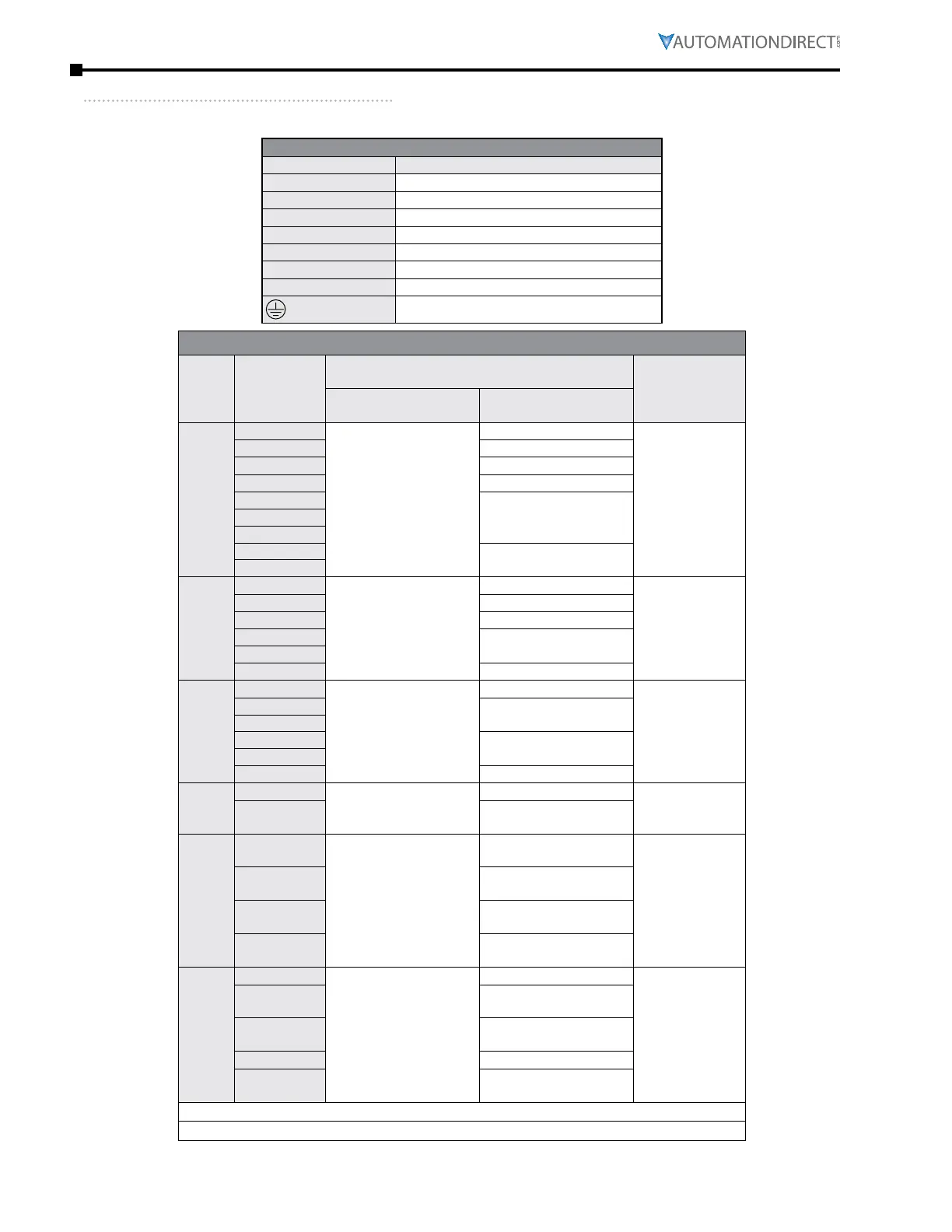
Main CirCUit wiring terMinals
main Terminal speCifiCaTions
Main Circuit Terminals
Terminal Description
R/L1
Input Power – phase 1
S/L2
Input Power – phase 2
T/L3
Input Power – phase 3
U/T1, V/T2, W/T3
AC Drive Output
+1, +2
DC Choke Connection (frames A–C)
B1, B2
Braking Resistor Connection (frames A–C)
+1/DC+, -/DC-
External Dynamic Brake Unit (frames D–G)
Ground
Main Circuit Wiring Specifications
AC
Drive
Frame
Size
AC Drive
Model
Wire Range
(AWG [mm
2
])
Terminal
Tightening
Torque
(kg·cm [lb·in])
Max Min
A
GS4-21P0
8 [8�4]
14 [2�1]
20 [17�4]
GS4-22P0
12 [3�3]
GS4-23P0
10 [5�3]
GS4-25P0
8 [8�4]
GS4-41P0
14 [2�1]
GS4-42P0
GS4-43P0
GS4-45P0
10 [5�3]
GS4-47P5
B
GS4-27P5
4 [21�2]
8 [8�4]
35 [30�4]
GS4-2010
6 [13�3]
GS4-2015
4 [21�2]
GS4-4010
8 [8�4]
GS4-4015
GS4-4020
6 [13�3]
C
GS4-2020
1/0 [53�5]
1 [42�4]
80 [69�4]
GS4-2025
1/0 [53�5]
GS4-2030
GS4-4025
4 [21�2]
GS4-4030
GS4-4040
2 [33�6]
D0
GS4-4050
2/0 [67�4]
1/0 [53�5]
81�6 [70�8]
GS4-4060
2/0 [67�4]
1/0 [53�5]*
D
GS4-2040
300 MCM [152]
4/0 [107]*
4/0 [107]
3/0 [85]*
200 [173]
GS4-2050
250 MCM [127]
4/0 [107]*
GS4-4075
3/0 [85]
2/0 [67�4]*
GS4-4100
300 MCM [152]
4/0 [107]*
E
GS4-2060
300 MCM x2 [152 x2]
4/0 x2 [107 x2]*
1/0 x2 [53�5 x2]
200 [173]
GS4-2075
3/0 x2 [85 x2]
2/0 x2 [67�4 x2]*
GS4-2100
4/0 x2 [107 x2]
3/0 x2 [85 x2]*
GS4-4125
1/0 x2 [53�5 x2]
GS4-4150
3/0 x2 [85 x2]
2/0 x2 [67�4 x2]*
* Wiring specifications for drives with optional conduit box
(continued next page)

 Loading...
