Appendix C: Digital and Analog I/O Parameter Maps
Page C–7
DuRApulse GS4 AC Drive User Manual – 1st Ed, Rev A - 10/20/2017
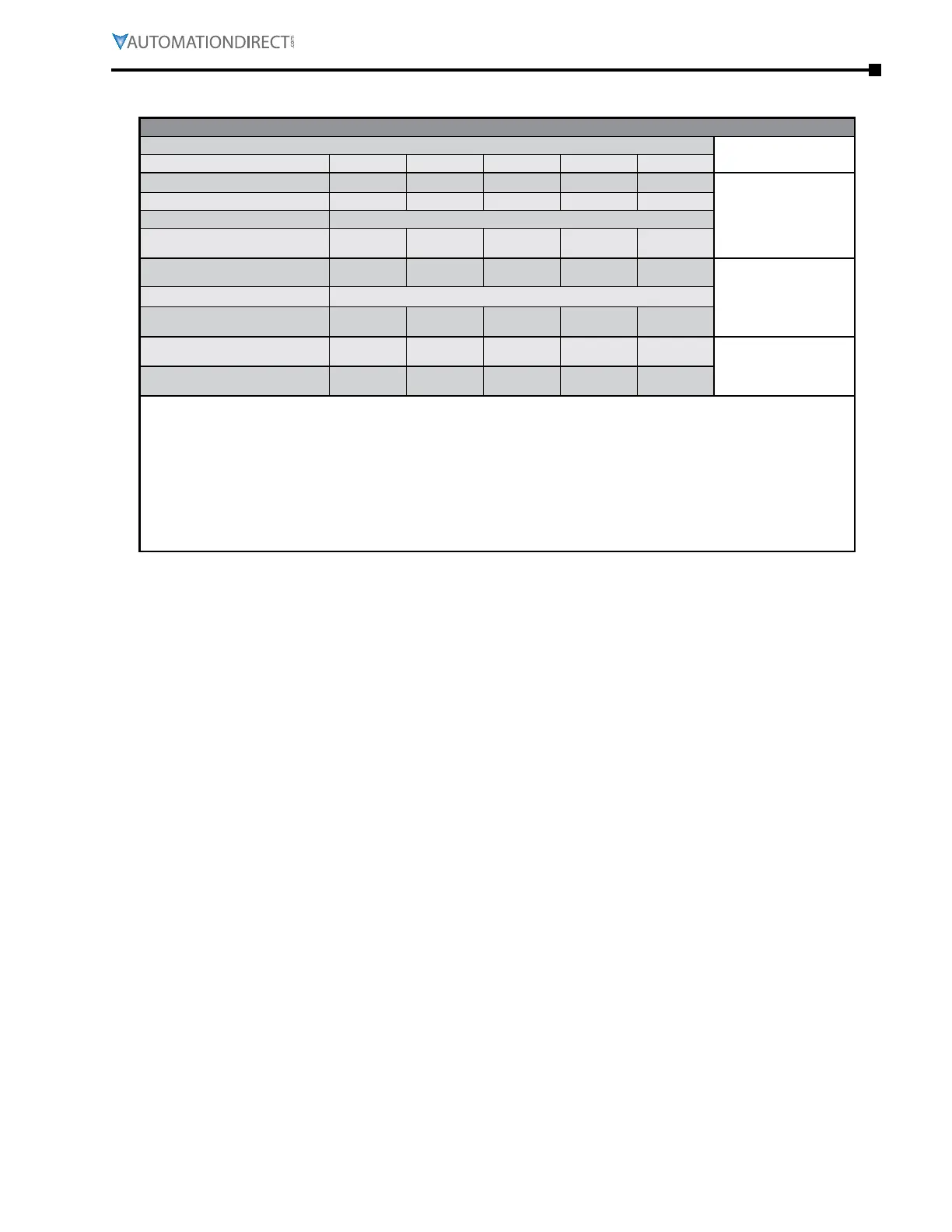
gs4 Digital OUtPUts – virtUal
GS4 Digital Outputs – Virtual *
Virtual Outputs *
Comments
PLC Address ** Y13 Y14 Y15 Y16 Y17
Parameter P3.27 P3.28 P3.29 P3.30 P3.31
Default Setting 0 0 0 0 0
Default Configuration No Function
User Defined
Selection / Value
DO - N�C� / N�O� Select
P3.43 - Bit #
B C D E F
(0 = N�O� / 1 = N�C�)
Default Configuration 0 = Normally Open
User Defined
Selection / Value
DO - Active Status Monitor
P3.47 - Bit #
B C D E F
Read Only!
DO - PLC Mask
P3.49 - Bit #
B C D E F
* GS4 virtual outputs can be used in the PLC while maintaining their Multi-Funciton setting when
reading P3.47. Parameters P3.27 thru P3.31 do not have an external termination point to wire to.
** Note for PLC Address: When an external output is used in the PLC and the PLC is in Run or Stop
mode, the PLC then controls that output and any Multi-Function Output setting assigned via
P3.17~P3.31 is void. To read the status of an output from the PLC while maintaining the MFO setting,
use the RPR command on the DO Status Register (P3.47). The ownership of the IO can be given back
to the drive by disabling the PLC either through the Keypad or Digital Inputs when they are assigned
values 36 and 37.

 Loading...
