Appendix D: Using GS4 AC Drives with AutomationDirect PLCs
Page D–7
DuRApulse GS4 AC Drive User Manual – 1st Ed, Rev A - 10/20/2017
drive analog inpuTs
The GS4 has 3 analog inputs (AI1, AI2 and AI3) that can be configured for a variety of input
functions. AI1 and AI2 must be configured via a Parameter (P4.05 or P4.06). They also have a DIP
switch located above the I/O terminal strip that allows them to be configured as voltage or current
inputs. AI3 is voltage input only. All three inputs have a variety of settings in Parameter Group 4
(P4.xx) that allows you to customize their scaling, offset, etc.
•
AI1: 0~10V, 4~20 mA, 0~20 mA (See P4.05 and the DIP switch AI1 above the I/O terminals)
•
AI2: 0~10V, 4~20 mA, 0~20 mA (See P4.06 and the DIP switch AI2 above the I/O terminals)
•
AI3: 0~10V, -10V to +10V
Connecting the analog inputs to PLC outputs is very straightforward. All three analog inputs share
the same common.
NOTE: The GS4 analog inputs do not supply the current when configured for 0~20 mA or 4~20
mA. The analog output device needs to supply the loop power.
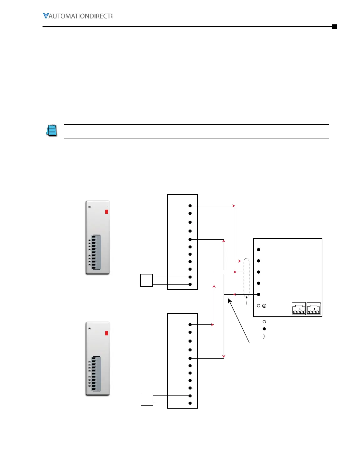
analog inpuT Wired for volTage and CurrenT
In this example, AI1 is configured for 0~10V (DIP switch and P4.05). AI2 is configured for 4~20 mA
(DIP switch and P4.06).
CLICK Expansion Module
C0-04DA-2
CH1
CH2
CH3
CH4
0V
0V
0V
0V
0V
24V
0V
C0-04DA-2
0-10V
OUTPUT
GS4-xxxx
+10V Power Source
(20mA max.)
AI1
(0 to 10V)
AI2
(0–20 mA or 4–20 mA)
AI3
(-10 to +10V)
ACM
Analog Signal Com.
18 18
See Power
Wiring Diag.
CH3
CH2
CH1
24V
0V
0V
0V
0V
0V
Output Module
Analog Current Sourcing
Output Module
Control circuit terminal
Shielded leads
Main circuit (power) terminals
4–20mA
0–10V
C0-04DA-2
CH4
0V
CH3
CH2
CH1
24V
0V
0V
0V
0V
0V
C0-04DA-1
CH4
0V
24VDC
Supply
Power
+
–
24VDC
Supply
Power
+
–
Analog Common
(same return path
for all three drive
analog inputs)
CLICK Expansion Module
C0-04DA-1
CH1
CH2
CH3
CH4
0V
0V
0V
0V
0V
24V
0V
C0-04DA-1
4-20mA
OUTPUT

 Loading...
