Chapter 2: Installation and Wiring
Page 2–17
DuRApulse GS4 AC Drive User Manual – 1st Ed, Rev A - 10/20/2017
CirCUit COnneCtiOns – warnings anD nOtes
Danger!
hAzARdous voltAGe! befoRe mAkING ANy coNNectIoN to the Ac dRIve, dIscoNNect All poWeR to the
Ac dRIve, ANd WAIt fIve mINutes foR dc bus cApAcItoRs to dIschARGe.
WARNING: ANy electRIcAl oR mechANIcAl modIfIcAtIoN to thIs equIpmeNt WIll voId All WARRANtIes,
mAy Result IN A sAfety hAzARd, ANd mAy voId the ul lIstING.
WARNING: do Not coNNect the Ac INput poWeR to the t1, t2, ANd t3 output teRmINAls. doING thIs
WIll dAmAGe the Ac dRIve.
WARNING: do Not coNNect sINGle-phAse poWeR to A thRee-phAse dRIve model.
WARNING: tIGhteN All scReWs to the pRopeR toRque RAtING. see “mAIN cIRcuIt WIRING” lAteR IN thIs
chApteR.
Wiring noTes: please read prior To insTallaTion.
1)
During installation, follow all local electrical, construction, and safety codes for the country in
which the AC drive is to be installed�
2)
Refer to the “dUrapUlse GS4 AC Drive Specifications” in chapter 1 for voltage and current
requirements�
3)
Torque the screws of the main circuit terminals to prevent loosening due to vibration�
4)
The addition of a magnetic contactor (MC) in the AC line power input wiring is recommended to
turn off power quickly and reduce the possibility of malfunction if the protection function of the
GS4 AC drive is activated� Both ends of the MC should have an R-C surge absorber�
5)
Do not use a power circuit contactor or disconnect switch for normal run/stop control of the
GS4 AC drive and motor� This will reduce the operating life cycle of the AC drive� Cycling
a power circuit switching device while the AC drive is in run mode should be done only in
emergency situations�
6)
Make sure the appropriate protective devices (circuit breaker or fuses) are connected between
the power supply and AC drive�
7)
Make sure that the leads are connected correctly and that the GS4 AC drive is properly
grounded. (Ground resistance should not exceed 0.1Ω.)
8)
Use ground leads that comply with AWG/MCM standards and keep them as short as possible�
9)
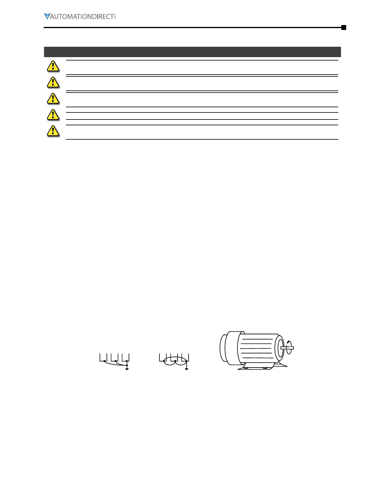
Multiple GS4 AC drives can be installed in one location� All of the units should be grounded
directly to a common ground terminal� The GS4 AC drive ground terminals may also be
connected in parallel, as shown in the figure below�
Make sure there are no ground loops�
Correct Incorrect
Forward
Running
10)
When the GS4 AC drive output terminals T1, T2, and T3 are connected to the motor terminals
T1, T2, and T3, respectively, the motor will rotate counterclockwise (as viewed from the shaft
end of the motor) when a forward operation command is received� To reverse the direction of
motor rotation, switch the connections of any of the two motor leads�
11)
Make sure that the power source is capable of supplying the correct voltage and required
current to the GS4 AC drive�
12)
Do not attach or remove wiring when power is applied to the GS4 AC drive�
13)
Do not inspect components unless inside “POWER” lamp is turned off�

 Loading...
