Appendix E: Safe Torque Off
Page E–3
DuRApulse GS4 AC Drive User Manual – 1st Ed, Rev A - 10/20/2017
wirinG DiaGramS
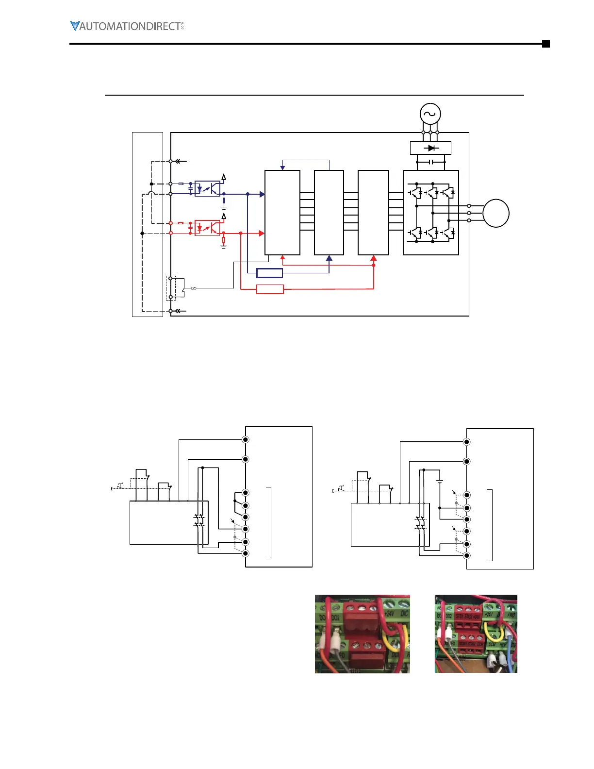
internal sto circuit
In the figure below, the factory setting for +24V-STO1-STO2 and SCM1-SCM2-ECM is short circuit
CP U
Line
drive
Factory-
Installed
Jumper
Gate
M
drive
EC M
DO
DOC
STO1
SC M1
SCM2
STO2
+24V
A
B
C
D
BUFFER
BUFFER
control looP wiring diagraMs
1)
Remove the jumper from +24V–STO1–STO2 and ECM–SCM1–SCM2�
2)
Wire the STO circuit like the diagrams below� The ESTOP contacts must be in a closed state
while in a normal and safe situation for the drive to be able to run�
3)
When the ESTOP switch is opened, the Safety PLC or Relay will open both sets of contacts� The
drive output will immediately stop, and the keypad will display an STO fault�
SCM1
STO1
+24V
STO2
ECM
Safety PLC
or
Safety Relay
SCM2
GS4
R1C or R1O
(Setting = 56 or 57)
R1
NOHC*
NOHC*
Red
STO
Terminals
Safety Relay On/Reset
2*
*2) Remove factory-installed short-circuit
jumper from +24V–STO1–STO2 when
using STO function with internal +24VDC.
STO Wiring with Internal +24VDC
*NOHC = Normally Open,
Held Closed
SCM1
STO1
+24V
STO2
ECM
Safety PLC
or
Safety Relay
SCM2
+24VDC
GS4
R1C or R1O
(Setting = 56 or 57)
R1
NOHC*
NOHC*
Red
STO
Terminals
Safety Relay On/Reset
*1,2) Remove factory-installed short-circuit
jumpers from red STO terminals when
using STO function with external +24VDC.
STO Wiring with External (user-supplied) +24VDC
1*
2*
*NOHC = Normally Open,
Held Closed
*1: Factory short-circuit of ECM–SCM1–SCM2.
To use Safety Function with external
power source, remove this jumper.
*2: Factory short-circuit of +24V–STO1–
STO2. To use Safety Function, remove this
jumper.
STO Terminals with Jumpers
STO Terminals without
Jumpers

 Loading...
