Appendix B: Optional I/O and Communication Cards
Page B–5
DuRApulse GS4 AC Drive User Manual – 1st Ed, Rev A - 10/20/2017
OPtiOnal i/O CarDs
The following chart lists the optional input/output cards available for GS4 series drives.
GS4 Optional I/O Cards *
Part Number Description Placement
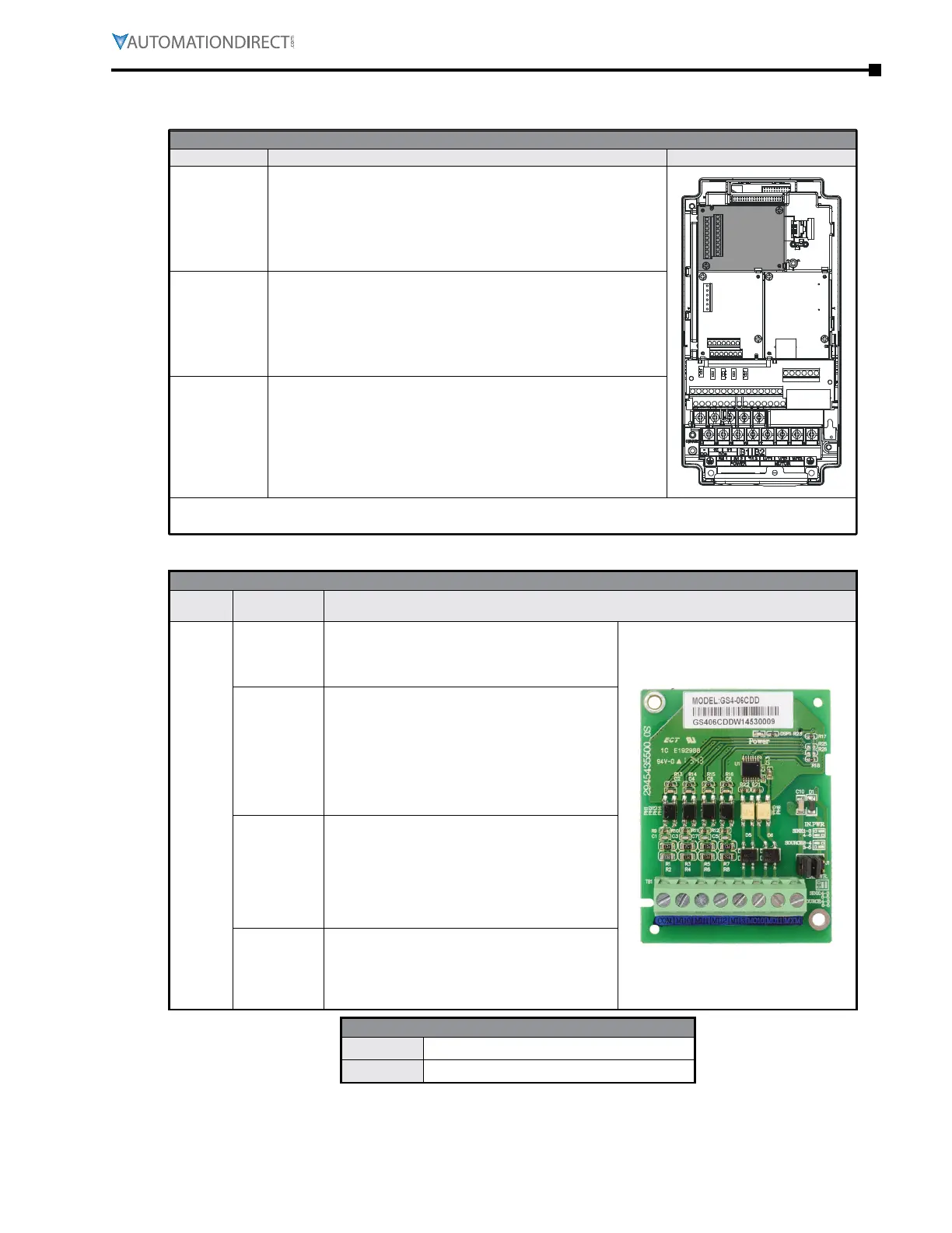
GS4-06CDD *
DuRApulse combination discrete I/O module, selectable sinking
or sourcing 24VDC input, 24VDC output, 4-point input, 2-point
output, 1 input common(s), 1 output common(s), 50mA resistive
output current� For use with GS4 series AC drives�
Slot 1Slot 2
(factory-installed card)
Slot 3
GS4-06NA *
DuRApulse discrete input module, sinking 120VAC input, 6-point
input, 1 input common(s)� For use with GS4 series AC drives�
GS4-06TR *
DURA
pulse relay output module, Form A (SPST) relays, 6-point
output, 6 output common(s)� For use with GS4 series AC drives�
* I/O cards can be installed only in Slot #3 of the GS4 drive, and only one I/O card at a time can be
installed.
gs4-06Cdd Combo i/o Card
GS4-06CDD - 4 DC Inputs / 2 DC Outputs
Part
Number
Terminals Description
GS4-
06CDD
COM
Common for Multi-Function Input terminals
Select SINK(NPN)/SOURCE(PNP) and internal/
external power supply with J1 jumper� Jumper is
only applicable to the inputs
DI10~DI13
Refer to parameters P3�11~P3�14 to program the
multi-function inputs DI10~DI13�
Internal power is applied from terminal E24:
+24VDC ±5% 200mA, 5W
External power +24VDC: max� voltage 30VDC,
min� voltage 19VDC
ON: the activation current is 3.3mA @ ≥ 11VDC
OFF: leakage current tolerance is 1.4mA ≤ 5VDC
DO10~DO11
Refer to P3�21 and P3�22 to program the multi-
function outputs DO10-DO11
Multi-function output terminals (photocoupler)
Duty-cycle: 50% ±5%
Max� output frequency: 100Hz
Max� current: 50mA
Max� voltage: 48VDC
DOC
Common for multi-function output terminals
DO11~DO11 (photocoupler)
Max 48VDC 50mA
Outputs are bi-directional (can be wired sink or
source)
GS4-06CDD Terminal Torque Specs
Wire Gauge 20~24 AWG
Torque 3�47 in·lb (0�39 N·m)

 Loading...
