Appendix A: Accessories
Page A–31
DuRApulse GS4 AC Drive User Manual – 1st Ed, Rev A - 10/20/2017
flange MOUnting kits
Optional GS4 drive flange mounting kits allow the heat sinks on the back of select GS4 drives to be
positioned through the back of the control enclosure. Since a majority of the heat generated by
the GS4 drive will be outside the enclosure, heat load will be reduced and a smaller enclosure may
possibly be used. These flange mounting kits are applicable to GS4 drive frame sizes A through
C. Frames D0, D, E, and F have integral flange mounting hardware (see cutout dimensions below).
Frame size G cannot be flange-mounted.
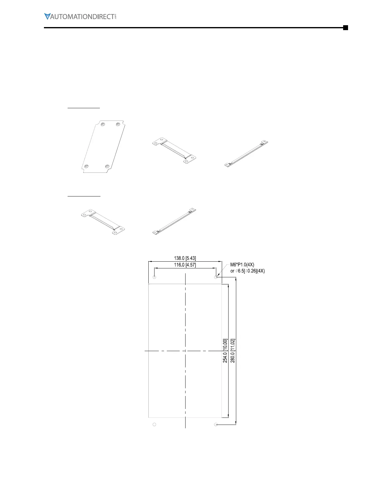
flange mounTing kiTs – frame a
GS4-FMKIT-1
Applicable models: GS4-22P0; GS4-23P0; GS4-43P0
Screw 1 - Qty� 4
M3*P 0�5; L=6mm
Screw 2 - Qty� 8
M6*P 1�0; L=16mm
Accessory 1 - Qty� 1 Accessory 2 - Qty� 2 Accessory 3 - Qty� 2
Protection Ratings
Top Cover Removed:
IP20/UL Open Type
Standard w/Top Cover:
IP20/UL Type 1/NEMA 1
GS4-FMKIT-A
Applicable models: GS4-21P0; GS4-25P0; GS4-41P0; GS4-42P0; GS4-45P0; GS4-47P5
Screw 2 - Qty� 8
M6*P 1�0; L=16mm
Accessory 2 - Qty� 2 Accessory 3 - Qty� 2
Frame A Cutout Dimensions mm [in]

 Loading...
