Appendix C: Digital and Analog I/O Parameter Maps
Page C–5
DuRApulse GS4 AC Drive User Manual – 1st Ed, Rev A - 10/20/2017
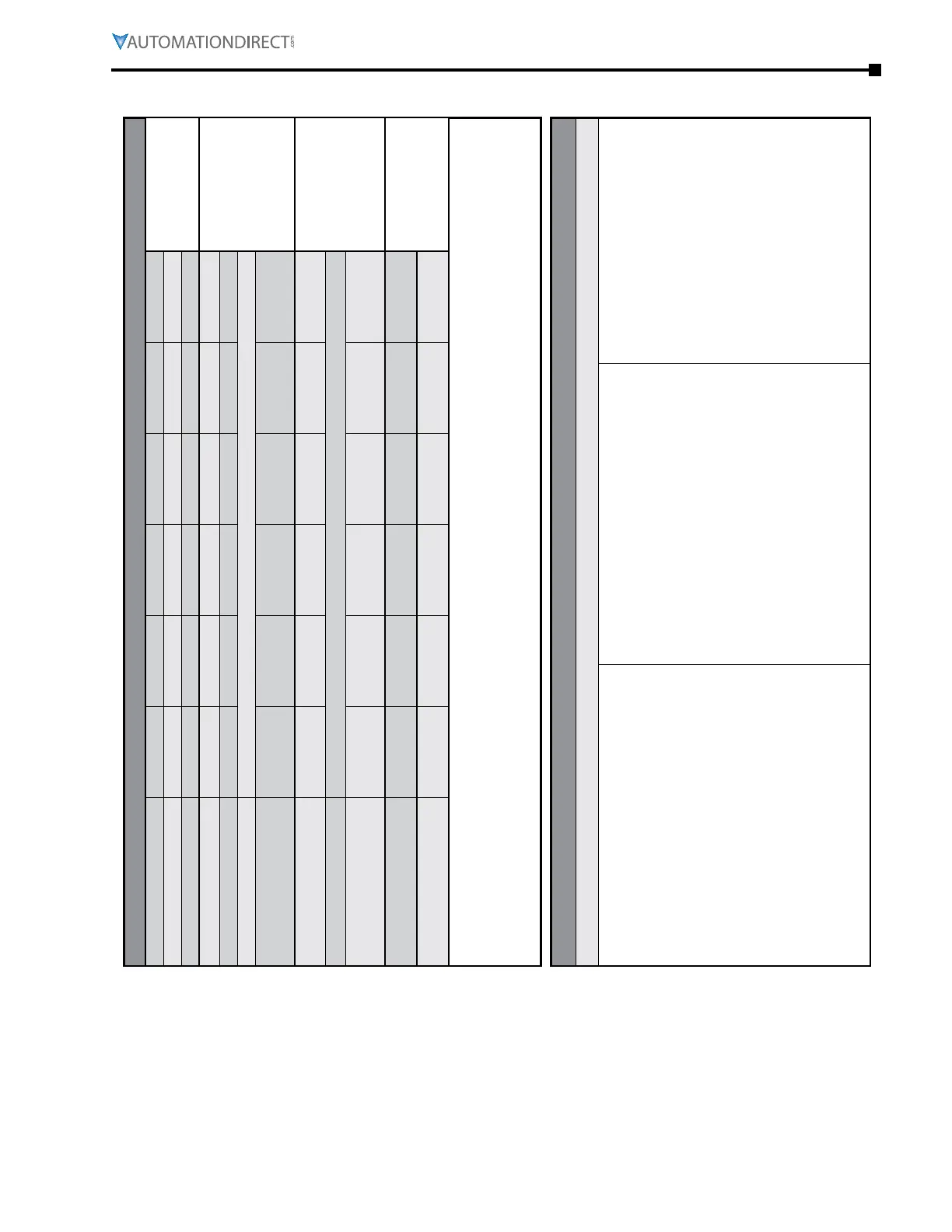
gs4 Digital inPUts – OPtiOn CarDs
GS4 Digital Inputs - Option Cards
GS4-06NA Terminals DI10 DI11 DI12 DI13 DI14 DI15
CommentsGS4-06CDD Terminals DI10 DI11 DI12 DI13 N/A N/A
PLC Address * X12 X13 X14 X15 X16 X17
Parameter P3.11 P3.12 P3.13 P3.14 P3.15 P3.16
See Digital Input
Configurations
Below
Default Setting 0 0 0 0 0 0
Default Configuration No Function
User Defined
Selection / Value
DI - N�C� / N�O� Select
P3.42 - Bit #
A B C D E F
(0 = N�O� / 1 = N�C�)
Default Configuration 0 = Normally Open
User Defined
Selection / Value
DI - Active Status Monitor
P3.46 - Bit #
A B C D E F
Read Only!
DI - PLC Mask
P3.48 - Bit #
A B C D E F
* Note for PLC Address: When an external input is used in the PLC and the PLC is in Run or Stop mode, the PLC then
controls that input and any Multi-Function input setting assigned via P3.03~P3.16 is void. To read the status of an input
into the PLC while maintaining the MFI setting use the RPR command on the DI Status Register (P3.46). The control of the
IO can be given back to the drive by disabling the PLC either through the Keypad or Digital Inputs when they are assigned
values 36 and 37.
Digital Input Configurations
Parameters P3.11~P3.16
0: No function
1: Multi-Speed/PID Multi-Setpoint bit 1
2: Multi-Speed/PID Multi-Setpoint bit 2
3: Multi-Speed/PID Multi-Setpoint bit 3
4: Multi-Speed bit 4
5: Reset
6: JOG
7: Accel/Decel speed inhibit (Speed Hold)
8: 1st~4th Accel/Decel time selection, bit 0
9: 1st~4th Accel/Decel time selection, bit 1
10: Emergency Stop EF Input by P3�56 (EF error)
11: Base Block Input
12: reserved
13: Disable Auto Accel/Decel Time
14: Switch between drive settings 1 and 2
15: Operation speed command from AI1
16: Operation speed command from AI2
17: Operation speed command from AI3
18: Forced Ramp Stop by P3�56 (no error)
19: Digital Freq Up Command
20: Digital Freq Down Command
21: PID function Disable
22: Clear counter
23: Increment counter value (DI6 only)
24: FWD JOG
25: REV JOG
26: Emergency Stop EF1 (Coast stop)(EF1 error)
27: Signal Confirmation for Y-connection
28: Signal Confirmation for Delta connection
29: Disable EEPROM Write
30: Forced Coast Stop
31: Hand Contact for HOA Control
32: Auto Contact for HOA Control
33: LOCAL/REMOTE Selection
34: Drive Enable
35: Decel Energy Backup (DEB) Enable
36: PLC Mode select bit0
37: PLC Mode select bit1
38: Output MCR Auxiliary Confirmation
39: reserved
40: Fire mode and force drive run
41: Fire mode and maintain operation
42: Disable all motors
43: Disable Motor #1
44: Disable Motor #2
45: Disable Motor #3
46: Disable Motor #4
47: Disable Motor #5
48: Disable Motor #6
49: Disable Motor #7
50: Disable Motor #8

 Loading...
