Page 2–34
DuRApulse GS4 AC Drive User Manual – 1st Ed, Rev A - 10/20/2017
Chapter 2: Installation and Wiring
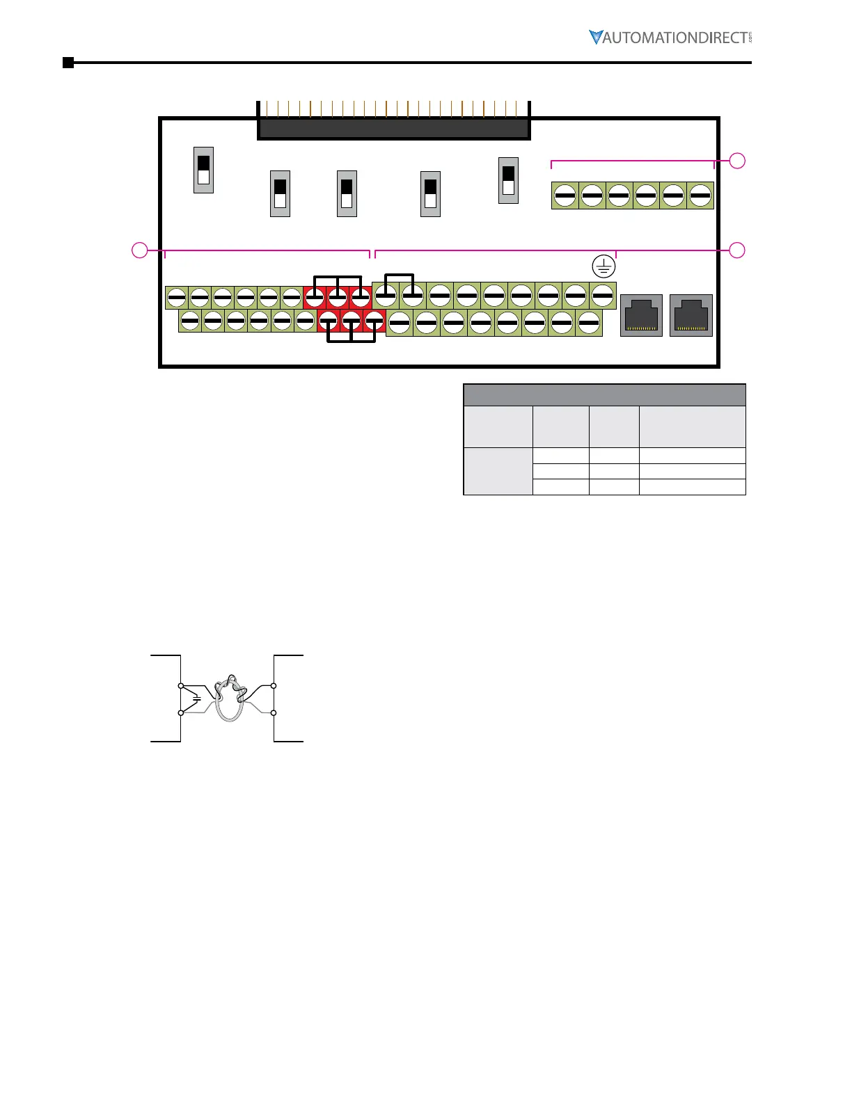
ConTrol Terminal bloCk diagram & Wiring speCifiCaTions
FWD DI1 DI3 DI5 DI7 SGND
DCM REV DI2 DI4 DI6 DI8 SG+ SG-
0~10V
-10~10V
SW1
SW2
RJ45-1RJ45-2
SW3
SW4
SW5
0~10V
0/4~20mA
AO2
AO1
0~10V
0/4~20mA
AI1
0/4~20mA
0~10V
AI2
Open
120Ω
485
Control circuit board is removable from the GS4 (for ease of wiring)
R2
R1O
R1CR1R2OR2C
A
BC
AO1 D01AI3AI1+10V D02D02
STO1 +24V
STO2
AO2 DOCACMAI2-10V FO
SCM1 ECM
SCM2
+24V DIC
•
SW1 sets AO1: 0~10V (default) or -10 to +10V
•
SW2 sets AO2: 0~10V (default) or 0/4–20mA
•
SW3 sets AI1: 0~10V (default) or 0/4–20mA
•
SW4 sets AI2: 0/4~20mA (default) or 0~10V
•
SW5 sets RS-485: open (default) or 120Ω
terminated
Control Circuit Wiring Specifications
AC Drive
Model
Terminal
#
Wire
Range
(AWG)
Tightening Torque
(kg·cm [lb·in])
GS4-xxxx
A 24~16 5 [4�3]
B 26~16 8 [6�9]
C 24~16 2 [1�7]
ConTrol Terminal Wiring insTruCTions
analog inpuTs
•
Analog input signals are easily affected by external noise� Use shielded wiring and keep it as short
as possible (<20m) with proper grounding� If the noise is inductive, connect the shield to terminal
ACM�
•
If the analog input signals are affected by noise from the AC motor drive, please connect a
capacitor and ferrite core as indicated in the following diagram�
(Wind each wire around the core 3 times or more�)
$,$,$,
$&0
IHUULWHFRUH
digiTal inpuTs
•
When using contacts or switches to control the digital inputs, use high quality components to
avoid contact bounce�
TransisTor ouTpuTs
•
Make sure to connect the digital outputs to the correct polarity�
•
When connecting a relay to the digital outputs, connect a surge absorber across the coil and
check the polarity�
analog ouTpuTs
•
When setting SW1, and using it as a current source (external 500Ω resistor is required), ensure
P4.53 AO1 0~20mA/4~20mA selection is set appropriately�
•
When seting SW2 to 0/4~20mA ensure to set P4.57 AO2 0~20mA/4~20mA selection
appropriately� When setting to 0~10V (or leaving as default) ensure P4�57 is set to zero�

 Loading...
