Chapter 8: GSLogic Introduction
Page 8–21
DuRApulse GS4 AC Drive User Manual – 1st Ed, Rev A - 10/20/2017
gs4 gslogic PrograM exaMPles
ex 1: gs4 drive control FroM gs4 Plc
Below is an example (available in the root directory where GSLogic was installed) in which the
drive PLC has control of the drive run, stop, direction, reset, and speed controls.
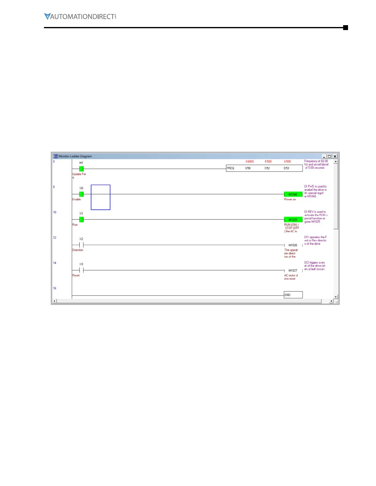
•
Rung 1: When bit M1 is on the FREQ instruction will write the values in D50, D52, and D53 to the
drive� This instruction will not cause the drive to run on its own� M1 can be turned on either via
Modbus or through GSLogic� The values of D50, D52, and D53 are populated using GSLogic by
modifying the register�
•
Rung 2: X0 (Digital input FWD) will turn on the output relay and allow power to the output of the
drive�
•
Rung 3: X1 (Digital input REV) will tell the drive to run at profile assigned in the FREQ command
in rung 1�
•
Rung 4: X2 (Digital input 1) will change the direction of rotation of the motor�
•
Rung 5: X3 (Digital input 2) will reset any resettable faults in the drive, if they occur�

 Loading...
