Page 2–6
DuRApulse GS4 AC Drive User Manual – 1st Ed, Rev A - 10/20/2017
Chapter 2: Installation and Wiring
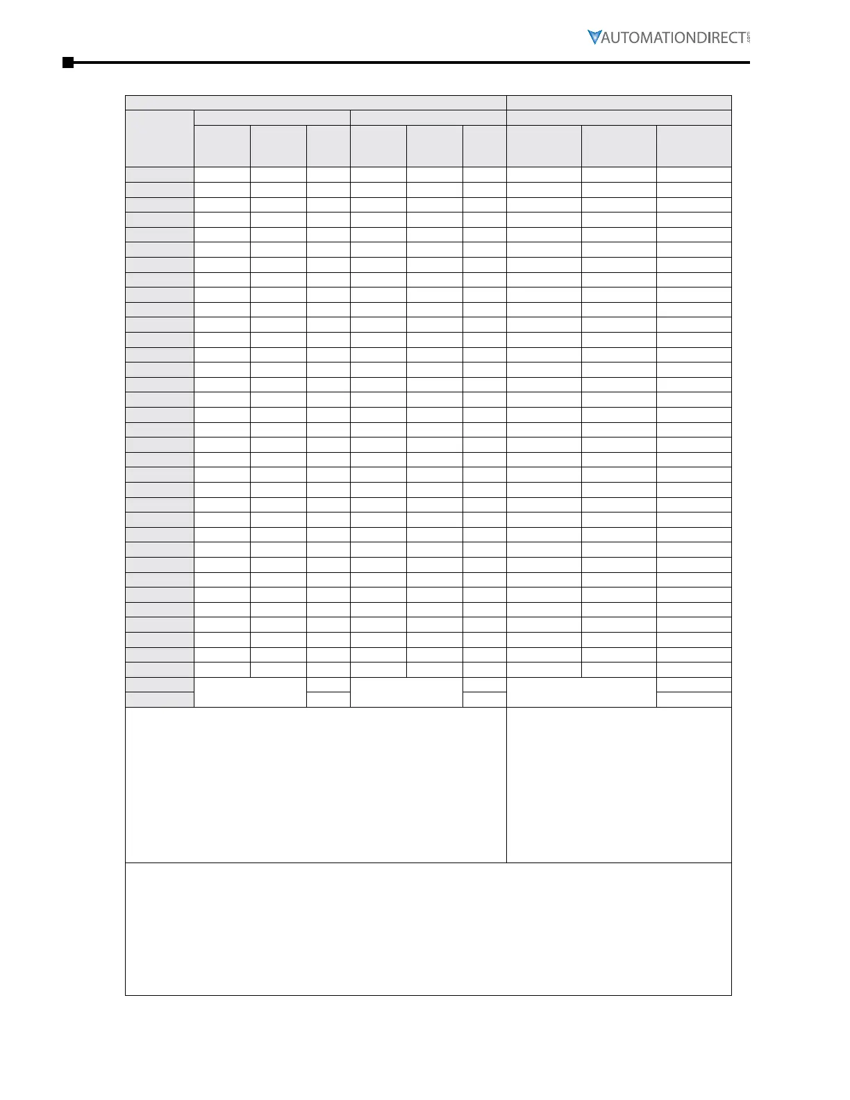
airfloW and poWer dissipaTion
Airflow Rate
1)
for Cooling Power Dissipation
Model
Number
Flow Rate
1)
(cfm) Flow Rate
1)
(m
3
/hr) Power Dissipation (Watt)
External Internal Total External Internal Total
Loss
External
(Heat sink)
Internal Total
GS4-21P0 – – – – – – 33 27 60
GS4-22P0 14 – 14 24 – 24 56 31 87
GS4-23P0 14 – 14 24 – 24 79 36 115
GS4-25P0 10 – 10 17 – 17 113 46 159
GS4-27P5 40 14 54 68 24 92 197 67 264
GS4-2010 66 14 80 112 24 136 249 86 335
GS4-2015 58 14 73 99 24 123 409 121 530
GS4-2020 166 12 178 282 20 302 455 161 616
GS4-2025 166 12 178 282 20 302 549 184 733
GS4-2030 166 12 178 282 20 302 649 216 865
GS4-2040 179 30 209 304 51 355 913 186 1099
GS4-2050 179 30 209 304 51 355 1091 220 1311
GS4-2060 228 73 301 387 124 511 1251 267 1518
GS4-2075 228 73 301 387 124 511 1401 308 1709
GS4-2100 246 73 319 418 124 542 1770 369 2139
GS4-41P0 – – – – – – 33 25 58
GS4-42P0 – – – – – – 45 29 74
GS4-43P0 14 – 14 24 – 24 71 33 104
GS4-45P0 10 – 10 17 – 17 103 38 141
GS4-47P5 10 – 10 17 – 17 134 46 180
GS4-4010 40 14 54 68 24 92 216 76 292
GS4-4015 66 14 80 112 24 136 287 93 380
GS4-4020 58 14 73 99 24 123 396 122 518
GS4-4025 99 21 120 168 36 204 369 138 507
GS4-4030 99 21 120 168 36 204 476 158 634
GS4-4040 126 21 147 214 36 250 655 211 866
GS4-4050 179 30 209 304 51 355 809 184 993
GS4-4060 179 30 209 304 51 355 929 218 1147
GS4-4075 179 30 209 304 51 355 1156 257 1413
GS4-4100 186 30 216 316 51 367 1408 334 1742
GS4-4125 257 73 330 437 124 561 1693 399 2092
GS4-4150 223 73 296 379 124 503 2107 491 2598
GS4-4175 224 112 336 381 190 571 2502 579 3081
GS4-4200 289 112 401 491 190 681 3096 687 3783
GS4-4250
–
454
–
771
–
4589
GS4-4300 454 771 5772
• The required airflow shown in chart is for installing a single GS4 drive
in a confined space�
• When installing multiple GS4 drives, the required air volume would
be the required air volume for a single GS4 drive multiplied by the
number of GS4 drives�
• Heat dissipation shown in the chart is
for installing a single GS4 drive in a
confined space�
• When installing multiple drives, the
volume of heat dissipation should be
the heat dissipated by a single GS4
drive multiplied by the number of GS4
drives�
• Heat dissipation for each model is
calculated by rated voltage, current and
default carrier frequency�
1) External flow rate is across the heat sink.
Internal flow rate is through the chassis.
Published flow rates are the result of active cooling using fans; factory-installed in the drive.
Unpublished flow rates (-) are the result of passive cooling in drives without factory-installed
fans.
2) When calculating power dissipation (Watt Loss) use the total value if the drive is foot mounted,
or the internal value if the drive is flange mounted. Where only a total value is published, these
models cannot be flange mounted.

 Loading...
