Page D–16
DuRApulse GS4 AC Drive User Manual – 1st Ed, Rev A - 10/20/2017
Appendix D: Using GS4 AC Drives with AutomationDirect PLCs
eTherneT/ip moniTor and ConTrol
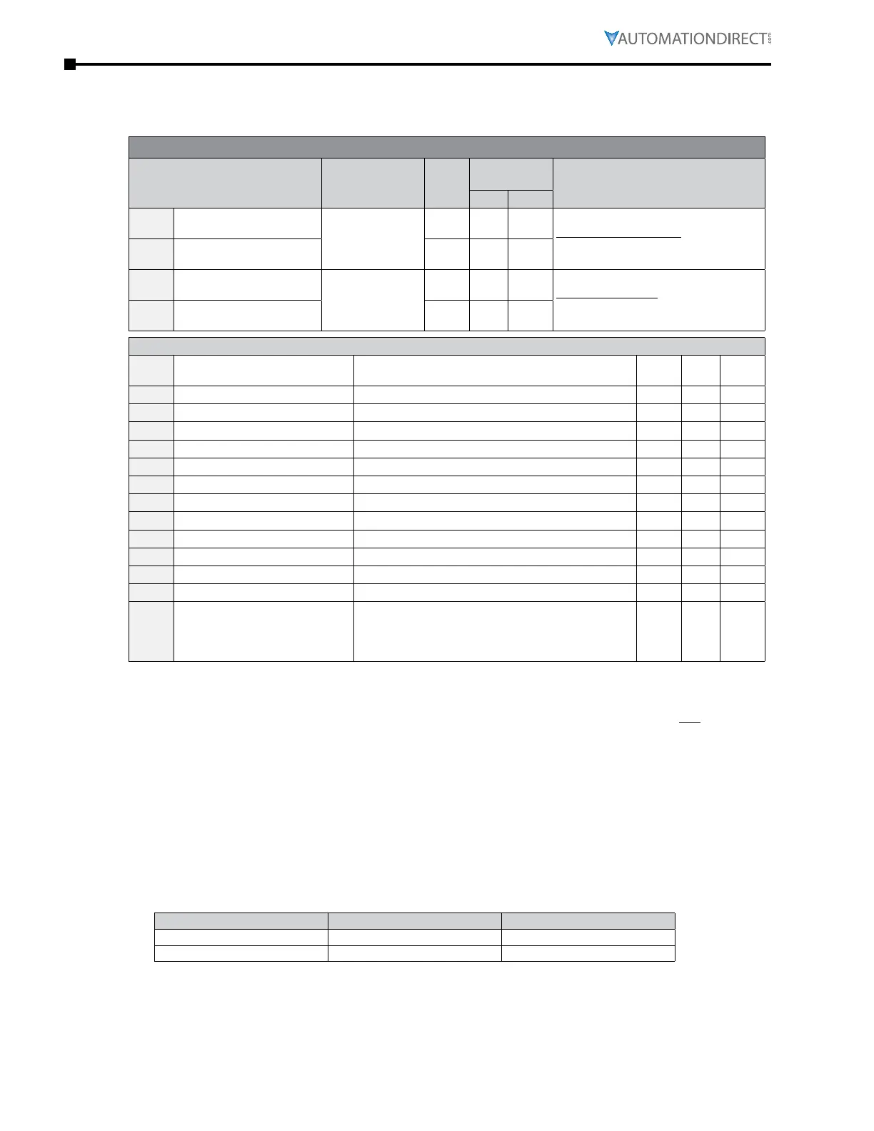
After installing the EtherNet/IP option card, set the following parameters:
(See Appendix B for more information on card installation.)
GS4 Parameter Settings for EtherNet/IP Monitor and Control
Parameter Setting
Run
1)
Read/
Write
Modbus
Address
Note
Hex Dec
P3.00
1st Source of Operation
Command [Remote]
5: Comm Card;
Keypad STOP
is enabled
R/W 0300 40769
This allows Ethernet commands to
start and stop the drive after the
REMOTE button is pressed (drive is in
REMOTE mode).
P3.01
2nd Source of Operation
Command [Local]
R/W 0301 40770
P4.00
1st Source of Frequency
Command [Remote]
4: Comm Card
♦R/W 0400 41025
This allows Ethernet commands to
set the drive speed after the REMOTE
button is pressed (drive is in REMOTE
mode).
P4.01
2nd Source of Frequency
Command [Local]
♦R/W 0401 41026
Other key parameters that must be modified (or at least must be known) to set up Ethernet communications
P9.48
Comm Card IP Configuration
0: Static IP
1: Dynamic IP (DHCP)
R/W 0930 42353
P9.49
Comm Card IP Address Octet 1 0~255 R/W 0931 42354
P9.50
Comm Card IP Address Octet 2 0~255 R/W 0932 42355
P9.51
Comm Card IP Address Octet 3 0~255 R/W 0933 42356
P9.52
Comm Card IP Address Octet 4 0~255 R/W 0934 42357
P9.53
Comm Card Mask Octet 1 0~255 R/W 0935 42358
P9.54
Comm Card Mask Octet 2 0~255 R/W 0936 42359
P9.55
Comm Card Mask Octet 3 0~255 R/W 0937 42360
P9.56
Comm Card Mask Octet 4 0~255 R/W 0938 42361
P9.57
Comm Card Gateway Octet 1 0~255 R/W 0939 42362
P9.58
Comm Card Gateway Octet 2 0~255 R/W 093A 42363
P9.59
Comm Card Gateway Octet 3 0~255 R/W 093B 42364
P9.60
Comm Card Gateway Octet 4 0~255 R/W 093C 42365
P9.64
Comm Card External Set
0, 2
Bit 0 = reserved
Bit 1 = Write Ethernet Parameters to Comm Card
Bit 2 = reserved
R/W 0940 42369
Refer to Appendix B for detailed information and an example on how to set up these parameters.
We recommend using Static IP (P9.48=0) and testing the communications between drive and
PC/PLC with either an Ethernet crossover cable or a simple Ethernet hub/switch. Do not try to
commission Ethernet communications for the first time on a larger, managed network.
Set P9.64 = 2 (bit 1) after changing any of these parameters to save the changes to the card firmware.
Appendix B details all the Implicit and Explicit data that can be transferred to and from the GS4.
Below is a list of the Implicit (I/O messaging) data that will be automatically transferred back and
forth between the PLC and drive once the connection is configured.
gs4-Cm-eneTip eTherneT/ip i/o messaging (impliCiT messaging)
•
Trigger type: Cyclic
•
Transport class: 1
•
Application behavior: Exclusive owner
Parameter O→T T→O
Data size Fixed Fixed
Connection type Multicast, Point to Point Mulitcast, Point to Point
gs4-Cm-eneTip eTherneT/ip CommuniCaTion parameTer
•
Input buffer register: In Assembly Instance = 101, Width = 16 bits, Size = 16
•
Output buffer register: Out Assembly Instance = 100, Width = 16 bits, Size = 3
•
Configuration: Instance = 102, Width = 8 bits, Size = 0

 Loading...
