Page 2–32
DuRApulse GS4 AC Drive User Manual – 1st Ed, Rev A - 10/20/2017
Chapter 2: Installation and Wiring
COntrOl CirCUit wiring terMinals
ConTrol Terminal speCifiCaTions
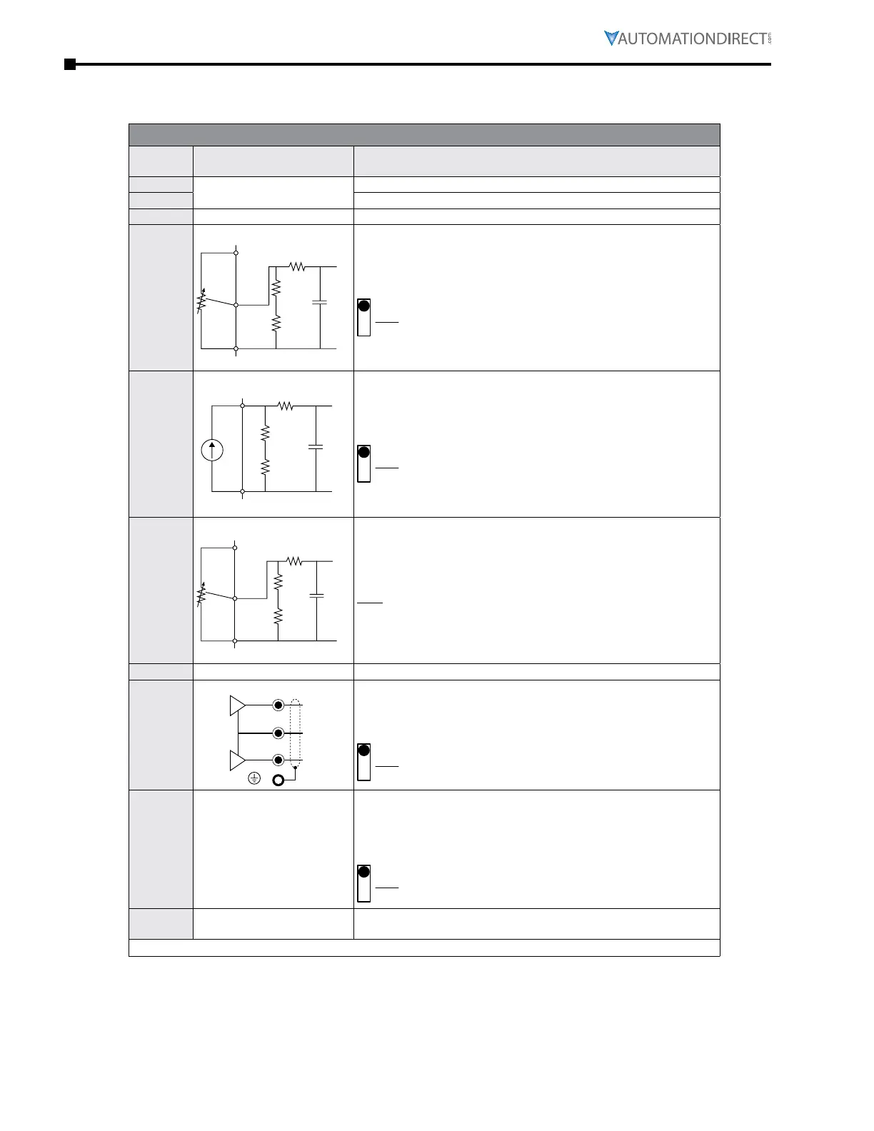
Control Circuit Terminals
Terminal
Symbol
Description Remarks
+10V
Potentiometer Power Supply
Analog frequency setting: +10VDC 20mA max output
-10V
Analog frequency setting: -10VDC 20mA max output
+24V
Digital Control Signal Source +24V±5%, 200mA max output; use with DCM
AI1
Analog Input 1
$&0
$,
$,FLUFXL
Impedance: 20kΩ
Range: 0~10V → 0/4~20mA = 0~Max Output Frequency
AI1 switch = SW3; factory setting is 0~10V
6:IRU$,
AI2
Analog Input 2
LQWHUQDOFLUFXLW
Impedance: 250Ω
Range: 0/4~20mA → 0~10V = 0~Max Output Frequency
AI2 Switch = SW4; factory setting is 0~20mA
6:IRU$,
AI3
Analog Input 3
$&0
$,
$,FLUFXLW
Impedance: 20kΩ
Range: -10 to +10 VDC = 0~Max Output Frequency
Note:
For -10V to +10V operation, connect the pot to +10V and -10V.
Keep the pot wiper connected to AI3.
ACM
Analog Common Common for analog terminals
AO1
Analog Output 1
ACM
AO2
-10 to 10V max output current 2mA; max load 5kΩ
Re solution: 0~10V corresponds to max operation frequency
Range: 0~10V → -10 to +10V
AO1 Switch = SW1, factory setting is 0~10V
6:IRU$2
AO2
Analog Output 2
(internal circuit same as
AO1)
0–10V max output current 2mA; max load 5kΩ
0–20mA max output current 20mA; max load 500Ω
Re solution: 0–10V corresponds to max operation frequency
Range: 0~10V → 0/4~20mA
AO2 Switch = SW2; factory setting is 0~10V
6:IRU$2
DIC
Digital Signal Common Rail
Common terminal for multi-function inputs;
Can be tied to DCM (for sinking) or to +24V (for sourcing)
(continued next page)

 Loading...
