Page C–10
DuRApulse GS4 AC Drive User Manual – 1st Ed, Rev A - 10/20/2017
Appendix C: Digital and Analog I/O Parameter Maps
gs4 analOg inPUt 3 ParaMeters
GS4 – AI3 Specific Parameters
Parameter Selection / Value Default
User
Selection
Terminals AI3 – ACM N/A N/A
PLC Address D1030 N/A N/A
P4.04
Analog Input 3 (AI3) Function
0: No function
1: Frequency command
2: Reserved
3: Reserved
4: Reserved
5: Reserved
6: PTC thermistor input value
11: PT100 (RTD) thermistor input value
0
P4.19
AI3 Input Bias (Offset) -100�0% to +100�0% 0
P4.20
AI3 Input Bias (Offset) Polarity
0: NO Offset
1: Positive Offset
2: Negative Offset
0
P4.21
+AI3 Input Gain -500�0% to +500�0% 100�0
P4.22
-AI3 Input Gain -500�0% to +500�0% 100�0
P4.23
AI3 Filter 0�00~20�00 sec 0�01
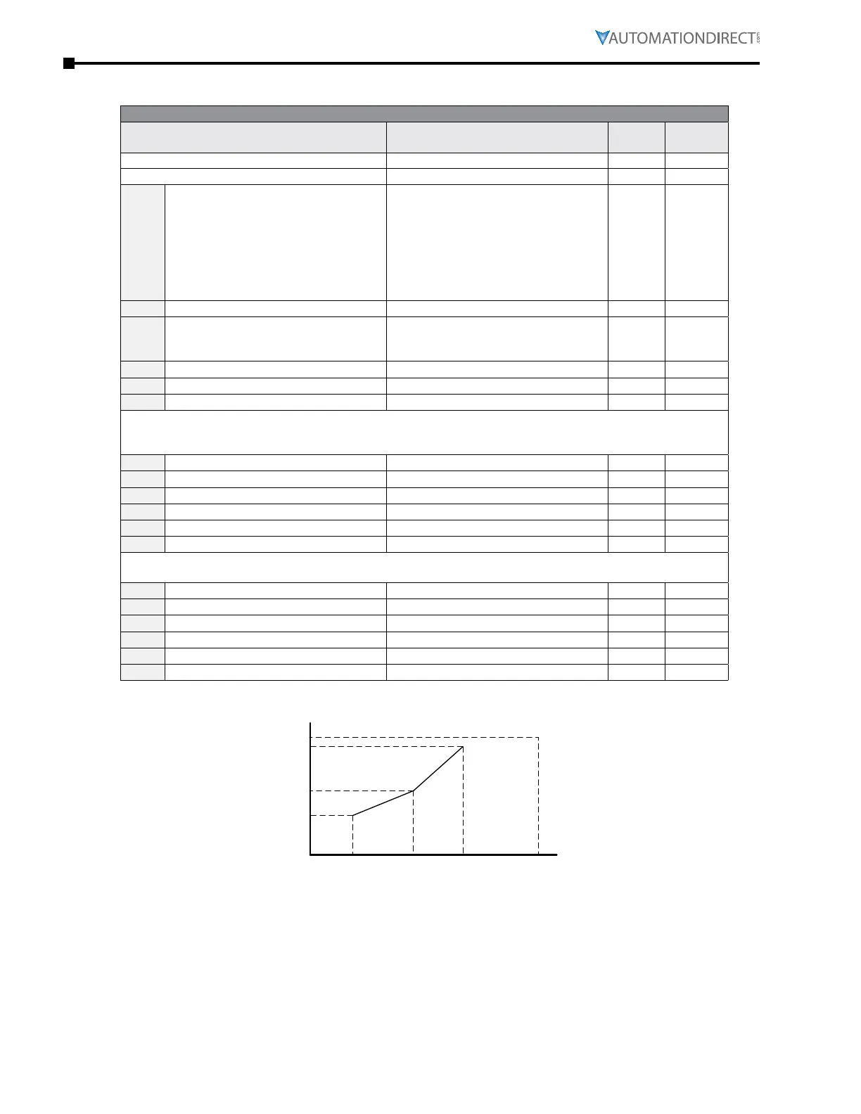
Parameters below are used to characterize the GS4 drive output frequency if using AI3 for speed reference.
If AI3 is unipolar (0 to 10V) – Parameters define the entire range of the signal. (0 to 10V)
If AI3 is bipolar (-10 to 10V) – Parameters define the positive half of the signal (from 0 to +10V)
P4.37
AI3 Low Voltage Unipolar 0�00~10�00V 0
P4.38
AI3 Low Hz Percent Unipolar 0�00~100�00% 0
P4.39
AI3 Mid Voltage Unipolar 0�00~10�00V 5�00
P4.40
AI3 Mid Hz Percent Unipolar 0�00~100�00% 50�00
P4.41
AI3 High Voltage Unipolar 0�00~10�00V 10�00
P4.42
AI3 High Hz Percent Unipolar 0�00~100�00% 100�00
If AI3 is unipolar (0 to 10V) – Parameters below are unused.
If AI3 is bipolar (-10 to +10V) – Parameters define the negative half of the signal (from -10 to 0V)
P4.43
-AI3 High Voltage Bipolar -10�00V to 0�00V 0�00
P4.44
-AI3 High Hz Percent Bipolar -100�00% to +100�00% 0�00
P4.45
-AI3 Mid Voltage Bipolar -10�00V to 0�00V –5�00
P4.46
-AI3 Mid Hz Percent Bipolar -100�00% to +100�00% –50�00
P4.47
-AI3 Low Voltage Bipolar -10�00V to 0�00V –10�00
P4.48
-AI3 Low Hz Percent Bipolar -100�00% to +100�00% –100�00
P0.04
Analog Input 3 (AI3) Custom Curve
Drive Hz Output
P4.42
P4.40
P4.38
P4.37 P4.39 P4.41 10V
Analog Input

 Loading...
