Appendix C: Digital and Analog I/O Parameter Maps
Page C–9
DuRApulse GS4 AC Drive User Manual – 1st Ed, Rev A - 10/20/2017
gs4 analOg inPUt 2 ParaMeters
GS4 – AI2 Specific Parameters
Parameter Selection / Value Default
User
Selection
Terminals AI2 – ACM N/A N/A
PLC Address D1029 N/A N/A
P4.03
Analog Input 2 (AI2)
Function
0: No Function
1: Frequency Command/PID Setpoint REMOTE
2: Frequency Command/PID Setpoint LOCAL
3: Frequency Command/PID Setpoint REMOTE & LOCAL
4: reserved
5: PID Feedback Signal
6: PTC Thermistor Input Value
7: PID Offset (Input)
8~10: reserved
11: PT100 Thermistor Input Value
0
P4.06
AI2 – I/V Selection
0: AI2i Selection (0~10V)
1: AI2v Selection (4~20mA)
2: AI2i Selection (0~20mA)
0
P4.15
AI2 Input Bias (Offset) -100�0% to +100�0% 0
P4.16
AI2 Input Bias (Offset)
Polarity
0: NO Offset
1: Positive Offset
2: Negative Offset
0
P4.17
AI2 Input Gain -500�0% to +500�0% 100�0
P4.18
AI2 Filter 0�00~20�00 sec 0�01
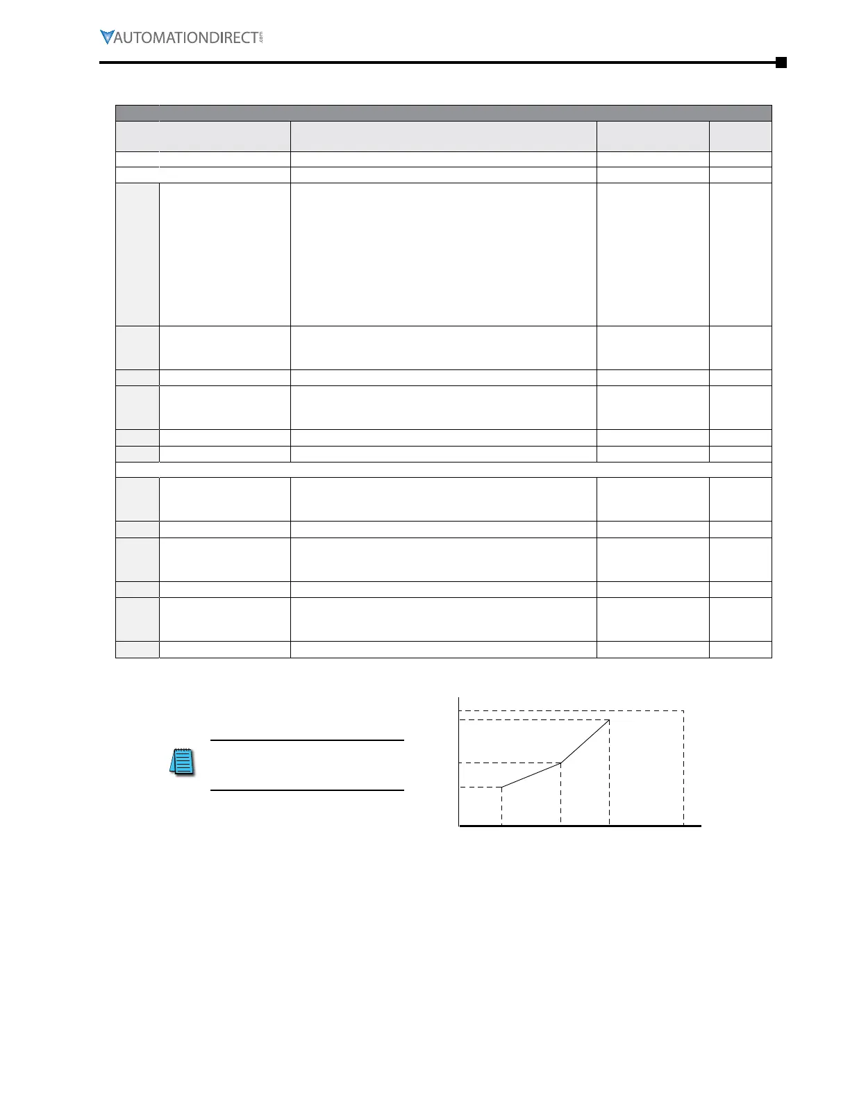
Parameters below are used to characterize the GS4 drive output frequency if using AI2 for speed reference.
P4.31
AI2 Low V/A
P4�06=0: 0�00~10�00V
P4�06=1: 4�00~20�00mA
P4�06=2: 0�00~20�00mA
P4 �06=0: 0�00V
P4 �06=1: 4�00mA
P4 �06=2: 0�00mA
P4.32
AI2 Low Hz Percent 0�00~100�00% 0
P4.33
AI2 Mid V/A
P4�06=0: 0�00~10�00V
P4�06=1: 4�00~20�00mA
P4�06=2: 0�00~20�00mA
P4 �06=0: 5�00V
P4 �06=1: 12�00mA
P4 �06=2: 10�00mA
P4.34
AI2 Mid Hz Percent 0�00~100�00% 50�00
P4.35
AI2 High V/A
P4�06=0: 0�00~10�00V
P4�06=1: 4�00~20�00mA
P4�06=2: 0�00~20�00mA
P4 �06=0: 10�00V
P4 �06=1: 20�00mA
P4 �06=2: 20�00mA
P4.36
AI2 High Hz Percent 0�00~100�00% 100�00
P4.49 (Loss of AI2) determines
the drive behavior if the
4~20mA signal is lost.
P0.04
Analog Input 2 (AI2) Custom Curve
Drive Hz Output
P4.36
P4.34
P4.32
P4.31 P4.33 P4.35
20mA/10V
Analog Input

 Loading...
