Page 2–30
DuRApulse GS4 AC Drive User Manual – 1st Ed, Rev A - 10/20/2017
Chapter 2: Installation and Wiring
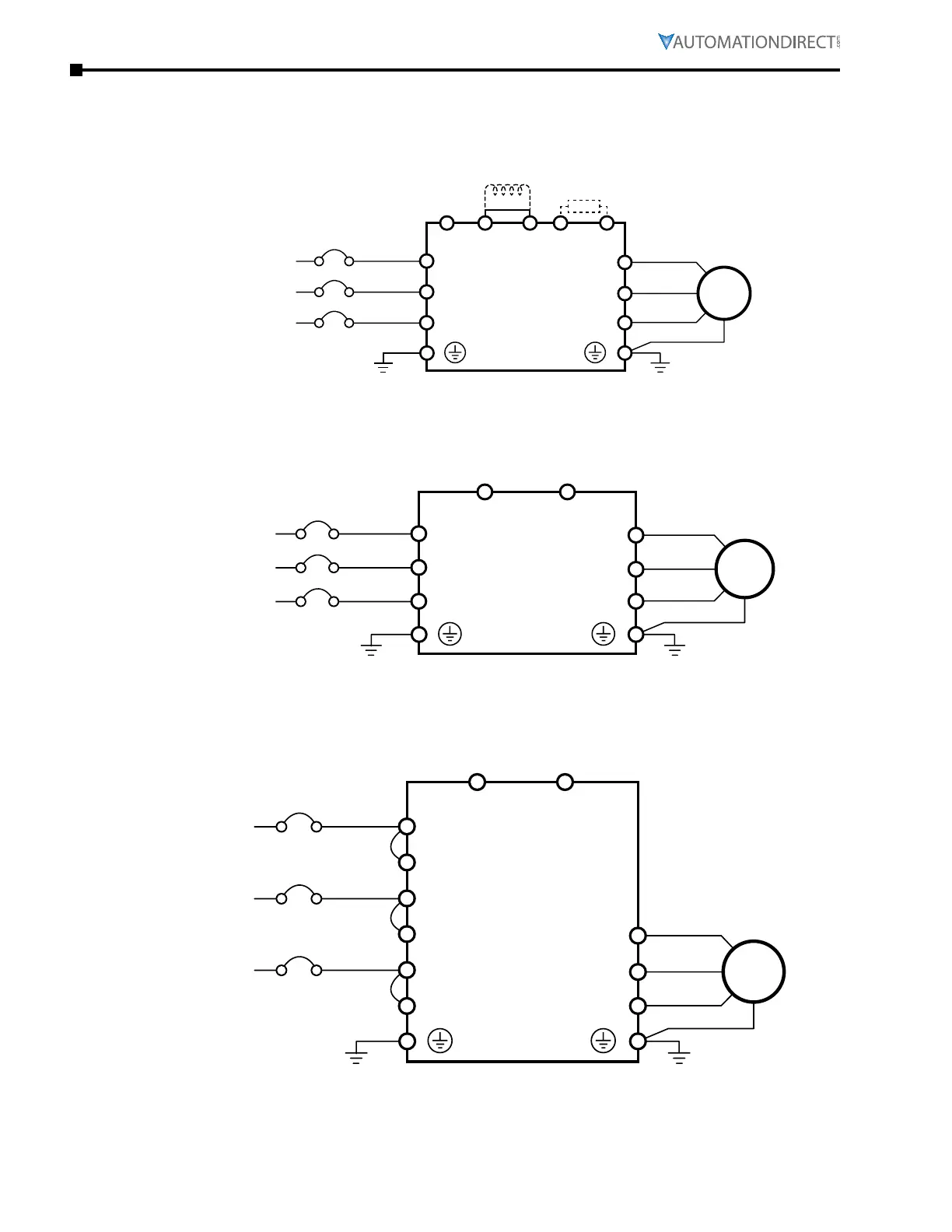
Main CirCUit wiring DiagraMs
frame sizes a, b, C main Wiring diagram, Three-phase
Motor
Provide 3-phase input power
Fuse / NFB (No Fuse Breaker)
(L1)
(L2)
(L3)
GS4-41P0 – GS4-4040 models
230/460VAC, 3-Phase
Includes frame sizes A, B, C
R(L1)
S(L2)
T(L3)
U(T1)
V(T2)
W(T3)
+2
Jumper
Brake resistor
(optional)
B1
B2
+1
–
DC choke
(optional)
3Ø
IM
frame sizes d0, d, e, f main Wiring diagram, Three-phase
Motor
3URYLGHSKDVHLQSXWSRZHU
Fuse / NFB (No Fuse Breaker)
(L1)
(L2)
(L3)
R(L1)
S(L2)
T(L3)
U(T1)
V(T2)
W(T3)
+1/DC+
–/DC–
GS4-4050 – GS4-200 models
230/460VAC, 3-Phase
Includes frame sizes D0, D, E, F
3Ø
IM
+1/DC+ & -/DC- terminals are for the connection of an optional
GS-xDBU dynamic braking unit.
Do NOT connect a braking resistor directly to terminals
+1/DC+ and -/DC-. Connecting a resistor directly to
these terminals will damage the GS4 drive!
frame size g main Wiring diagram, Three-phase
Motor
3URYLGHSKDVHLQSXWSRZHU
Fuse / NFB (No Fuse Breaker)
(L3)
GS4-4300 models
460VAC, 3-Phase
S(L22)
T(L31)
T(L32)
(L1)
(L2)
R(L11)
R(L12)
S(L21)
U(T1)
V(T2)
W(T3)
+1/DC+
–/DC –
3Ø
IM
+1/DC+ & -/DC- terminals are for the connection of an optional GS-xDBU
dynamic braking unit.
Do NOT connect a braking resistor directly to terminals
+1/DC+ and -/DC-. Connecting a resistor directly to
these terminals will damage the GS4 drive!

 Loading...
