Page 5–10
DuRApulse GS4 AC Drive User Manual – 1st Ed, Rev A - 10/20/2017
Chapter 5: Serial Communications
ConneCTing CommuniCaTion Cables
The GS4 AC drive includes an “RS-485” switch on the control board that will switch in a 120Ω
terminating resistor for the RS-485 network. an external terminating resistor is not required
for the drive end. An external termination resistor may be required on the other end of RS-
485 network; especially on long runs. Select resistors that match the impedance of the cable
(between 100Ω and 500Ω).
The DURApUlse GS4 serial communication port is an RS-485 input. Please note that terminals SG+
and SG- are shared with the RJ45 connectors. That means the user can use standard RJ45 patch
cables or industrial RS-485 cabling to access the comm port. GS4 to GS4 serial connections can be
accomplished with standard Ethernet patch cables (do not use cross-over cables). RS-232 signals
can be converted to RS-485 by using a separate converter (see the FA-ISOCON drawings on page
5–11).
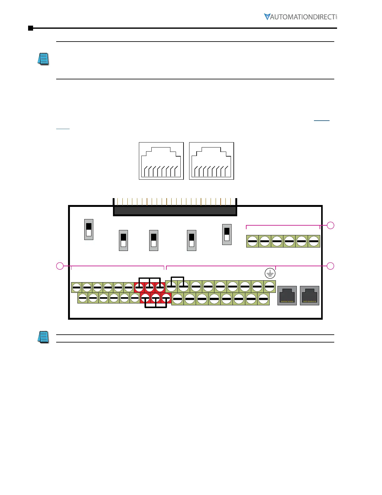
durapulse gs4 rs-485 serial Comm porTs
2: reserved
3: GND
4: SG–
5: SG+
6: GND
7: reserved
*
8: reserved*
GS4 Serial Comm Ports (2)
RS-485 Interface
18 18
* Reserved pins 1, 2, 7, & 8 are open and unused.
FWD DI1 DI3 DI5 DI7 SGND
DCM REV DI2 DI4 DI6 DI8 SG+ SG-
0~10V
-10~10V
SW1
SW2
RJ45-1RJ45-2
SW3
SW4
SW5
0~10V
0/4~20mA
AO2
AO1
0~10V
0/4~20mA
AI1
0/4~20mA
0~10V
AI2
Open
120Ω
485
Control circuit board is removable from the GS4 (for ease of wiring)
R2
R1O
R1CR1R2OR2C
A
BC
AO1 D01AI3AI1+10V D02D02
STO1 +24V
STO2
AO2 DOCACMAI2-10V FO
SCM1 ECM
SCM2
+24V DIC
Recommended RS-485 cable: Belden 9842 or equivalent.

 Loading...
