Page 8–8
DuRApulse GS4 AC Drive User Manual – 1st Ed, Rev A - 10/20/2017
Chapter 8: GSLogic Introduction
When the external Multi-Functional Input terminals (DI1 to DI8, P3.03 to P3.10) are set to function
36 or 37 (PLC Mode select bit0 or bit1), the digital inputs have priority and the keypad will not be
able to change PLC modes.
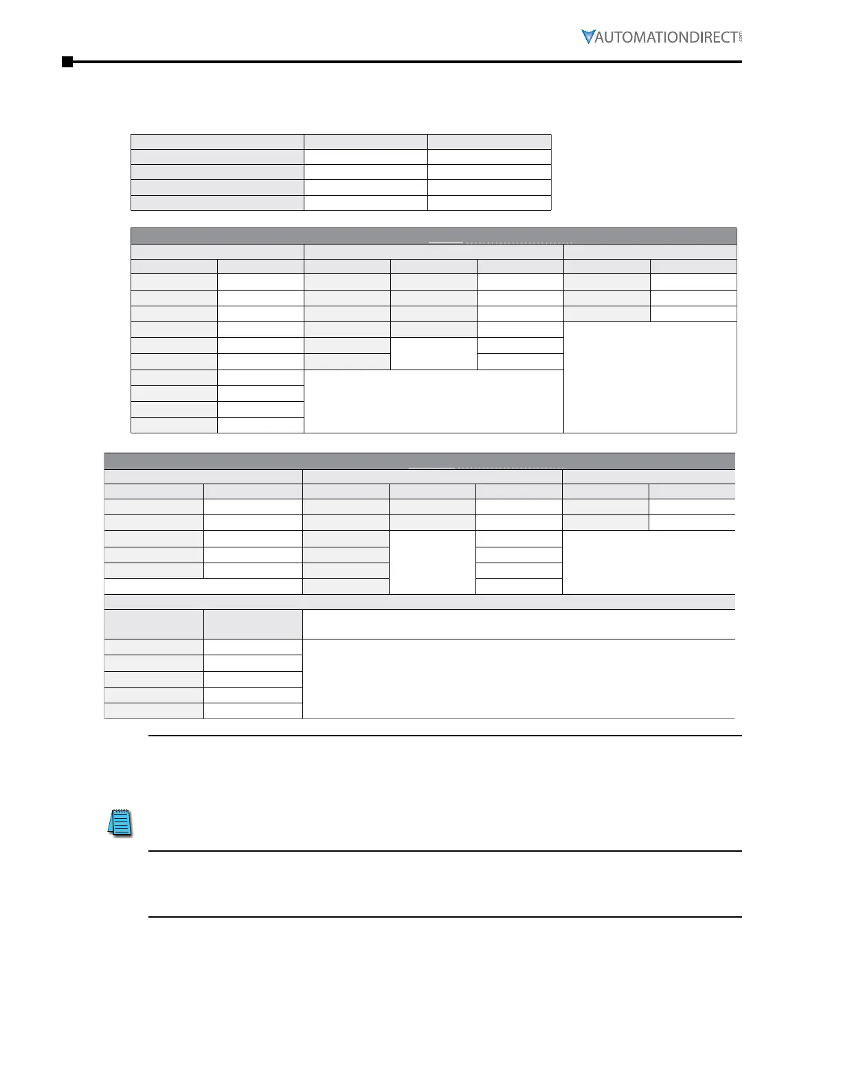
PLC Mode Select Bit1 (37) Select Bit0 (36)
Disable
OFF OFF
PLC Run
OFF ON
PLC Stop
ON OFF
Maintain Previous State
ON ON
GS4 AC Drive to PLC Input Cross Reference
GS4 Main Control Board DI GS4 Option Card DigitaI Inputs GS4 Main Control Board AI
GS4 Input PLC Address GS4-06NA GS4-06CDD PLC Address GS4 Analog PLC Address
FWD
X0
DI10 DI10
X12
AI1
D1028
REV
X1
DI11 DI11
X13
AI2
D1029
DI1
X2
DI12 DI12
X14
AI3
D1030
DI2
X3
DI13 DI13
X15
–
DI3
X4
DI14
–
X16
DI4
X5
DI15
X17
DI5
X6
–
DI6
X7
DI7
X10
DI8
X11
GS4 AC Drive to PLC Output Cross Reference
GS4 Main Control Board DO/RO GS4 Option Card DigitaI Outputs GS4 Main Control Board AI
GS4 Output PLC Address GS4-06TR GS4-06CDD PLC Address GS4 Analog PLC Address
R1-R1C-R1O
Y0
R10-RO10 DO10-DOC
Y5
AO1
D1040
R2-R2C-R2O
Y1
R11-RO11 DO11-DOC
Y6
AO2
D1045
reserved
Y2
R12-RO12
–
Y7
–
DO1-DOC
Y3
R13-RO13
Y10
DO2-DOC
Y4
R14-RO14
Y11
–
R15-RO15
Y12
GS4 Virtual Digital Outputs (PLC use only)
GS4 Virtual
Output
PLC Address
–
DO16
Y13
GS4 virtual outputs can be used as internal coils in the GS4 PLC� To monitor the
MFO status assigned to DO16~DO20, read P3�47 (Digital Output Status)�
DO17
Y14
DO18
Y15
DO19
Y16
DO20
Y17
NOTE 1: When X and Y addresses for the input and output terminals are included in the
PLC program, these input/output terminals will only be used by the PLC. The DI and DO
multifunction assignments are configured by parameters P3.03~P3.31 and will be overridden.
As an example, when the PLC program controls Y0 during PLC operation, the corresponding
output terminal relay (R1) will operate in accordance with the program. At this time, the
Multi-Function Output terminal setting P3.17 will be ineffective because these terminal
functions are already being used by the PLC.
NOTE 2: When the PLC uses the special registers D1040/D1045, the corresponding Analog
Outputs AO1/AO2 will only be used by the PLC overriding the multifunction configuration.
The AO multifunction assignments, when they are drive controlled, are configured by
parameters P4.50/P4.54.

 Loading...
