Page D–14
DuRApulse GS4 AC Drive User Manual – 1st Ed, Rev A - 10/20/2017
Appendix D: Using GS4 AC Drives with AutomationDirect PLCs
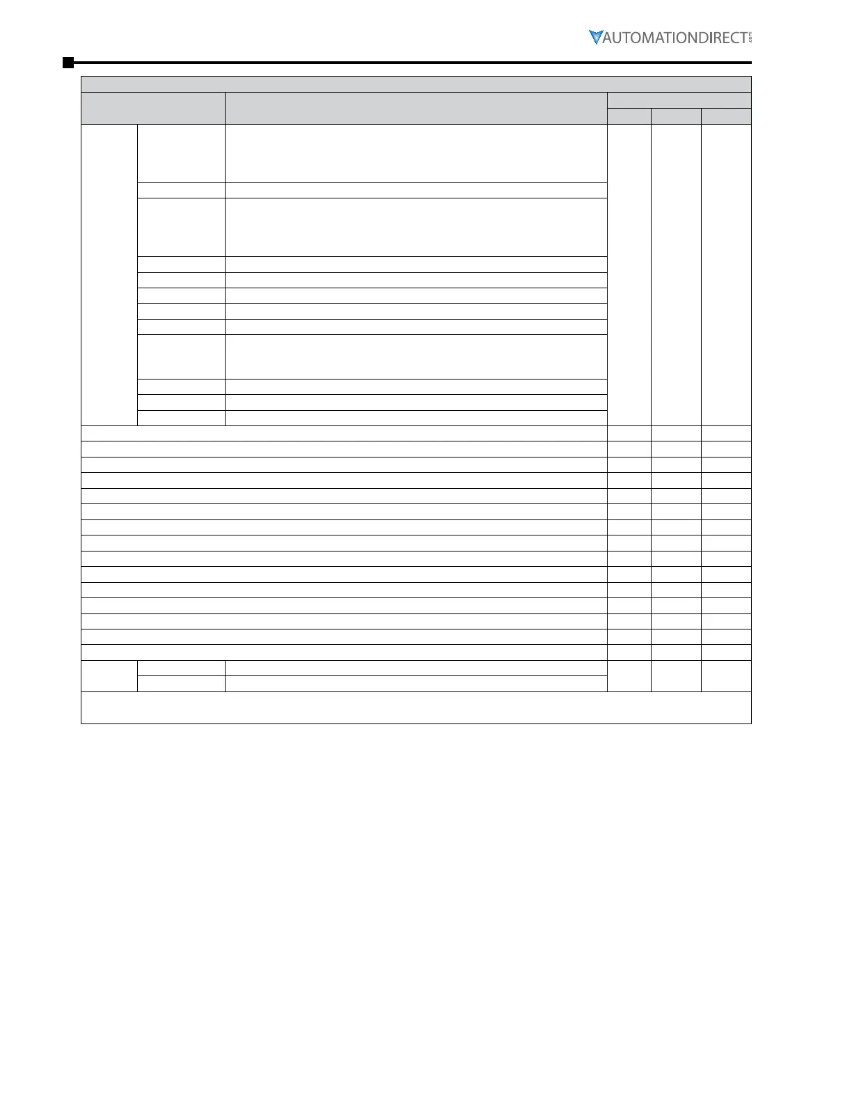
GS4 Status Addresses (Read Only) (continued)
Description Range
Modbus Address
Hex Dec Octal
Status
Monitor
2
Bit 0,1
0: Stop
1: Decelerate during the drive stopping
10: The drive standby
11: Run
2101 48450 20401
Bit 2 1: JOG active
Bit 3,4
0: FWD
1: REV to FWD
10: FWD to REV
11: REV
Bit 5 Reserved
Bit 6 Reserved
Bit 7 Reserved
Bit 8 1: Source of frequency by communication
Bit 9 1: Source of frequency by AI
Bit 10
1: Source of operation by communication
(If Keypad Stop is enabled (P3.00, P3.01 = 1,3,5), this bit will remain
“1” even if the source of operation is not communication.)
Bit 11 1: Parameters have been locked
Bit 12 Running Status (0: Drive Stopped; 1: Drive Running (including Standby))
Bit 13 to Bit 15 Reserved
Frequency command F (xxx.x) * 2102 48451 20402
Output Frequency H (xxx.x) 2103 48452 20403
Output Current A (xxx.x) 2104 48453 20404
DC-BUS Voltage U (xxx.x) 2105 48454 20405
Output Voltage E (xxx.x) 2106 48455 20406
Multi-Speed or PID Inputs current Step Number 2107 48456 20407
Active Warning 2108 48457 20410
DI6 Counter Value (must set P3.44) 2109 48458 20411
Power Factor angle ( cos θ) 210A 48459 20412
% Load 210B 48460 20413
Motor Actual Speed (rpm) 210C 48461 20414
PID Feedback Signal (pv) 210D 48462 20415
Reserved 210E 48463 20416
Reserved 210F 48464 20417
Reserved 2110 48465 20420
Error/
Warning
Low Byte Active Error [2100h = Active Error/Fault]
2118 48473 20430
High Byte Active Warning [2108h = Active Warning]
* If frequency command is greater than the Drive Maximum Output Frequency (P0.04), the GS4 drive will
accelerate to the Drive Maximum Output Frequency, as defined in (P0.04).

 Loading...
