Page 2–36
DuRApulse GS4 AC Drive User Manual – 1st Ed, Rev A - 10/20/2017
Chapter 2: Installation and Wiring
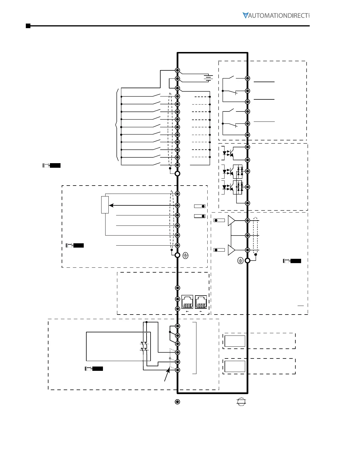
ConTrol CirCuiT Wiring diagrams (ConTinued)
full i/o WiTh sinking inpuTs
Control terminalsShielded leads & Cable
(field devices are sourcing)
AC Resistive:
250VAC / 3A (N.O.)
250VAC / 3A (N.C.)
Communication
extension card
Option
Slot 1
5kΩ
3
2
1
Option
Slot 3
81 81
Pin 1~2, 7, 8: reserved
Pin 3, 6:GND
Pin 4:SG-
Pin 5:SG+
DC Resistive:
30VDC / 5A (N.O.)
30VDC / 3A (N.C.)
AC Inductive:
250VAC / 1.2A (N.O.)
250VAC / 1.2A (N.C.)
Estimate at COS (0.4)
FWD/STOP* **
REV/STOP* **
Multi-step 1*
Multi-step 2*
Multi-step 3*
Multi-step 4*
N/A*
Multi-function output
terminals
I/O & RELAY
extension card
N/A*
N/A*
N/A*
+
AO1
SGND
SG+
SG-
DO1
DO2
DOC
FO
DCM
DCM
R1O
R2O
R2C
R2
+24V
FWD
DIC
REV
DI1
DI2
DI3
DI4
DI5
DI6
DI7
DI8
AO2
R1
R1C
+10V
-10V
AI1*
AI2*
AI3
ACM
ACM
Factory
setting
+24V, DCM =
internal 24VDC supply and 0V
DIC = Common rail
for all inputs (can be + or 0V)
For external power supply,
remove all wiring from all +24V
and DCM terminals
RJ
45-1
RJ
45-2
Analog Signal common
Analog Output 2 terminal
0~10VDC / 4~20mA
Analog Output 1 terminal
0~10VDC / -10~+10V
0~10V / 0~20mA / 4~20mA
0~20mA / 4~20mA / 0~10V
0~10V / -10 to +10V
+10V / 20mA
-10V / 20mA
Analog Signal Common
Modbus RS-485
BACnet
Internal
Power
Supply
NOTE
Do NOT apply mains voltage directly to above terminals.
** If P4.09 = 1, FWD/REV direction is controlled by analog input only.
SW3*
SW4*
* Ensure that the physical switches for AI1 and AI2
(located above the control terminal blocks) are
set for the correct voltage/current configuration.
NOTE
SW1*
SW2*
SCM1
STO1
+24V
STO2
ECM
Safety Relay,
Safety PLC,
or
E-Stop PB
(2 NC contacts required)
SCM2
NOHC
NOHC
Red
STO
Terminals
*
* Remove factory-installed short-circuit
jumper from +24V–STO1–STO2 when
using STO function with internal +24VDC.
NOTE
See User Manual Appendix E for STO details.
* Ensure that the physical
switches for AO1 and AO2
(located above the control
terminal blocks) are set for
the correct voltage/current
configuration. Use care to
set these switches correctly;
the setting positions are not
exactly the same for both.
NOTE
Digital Output terminals
5~48 VDC / 50mA
Digital Output terminals
5~48 VDC / 50mA
Multi-Function Output
Frequency terminals
5~30VDC / 30mA 100kHz
Digital Output common

 Loading...
