9. Lenses and adjustment
Image 9-2
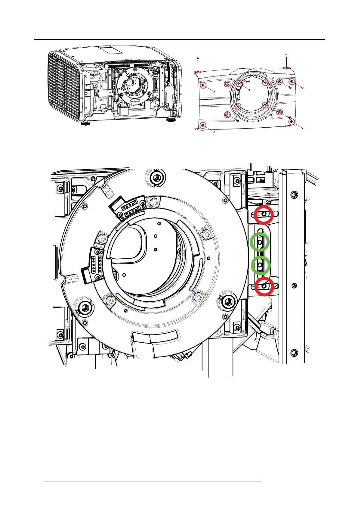
6. Insert M4 pan head s crews (not supplied) with a maximum length of 15mm in the threaded holes, indicated by the red and green
circles in the illustration below. Tighten the screws with a sufficient torque. The green c
ircles indicate the lock for the vertical shift,
and the red circles indicate the lock for the horizontal shift. All four lock ing positions mus t be used to achieve a sufficient locking.
Image 9-3
42 723–0016 F90 01/12/2017