20. Scheduled operations
The Liquid Cooling system consists of 5 se ts, 2 for each Laser cluster and one for the DM D.
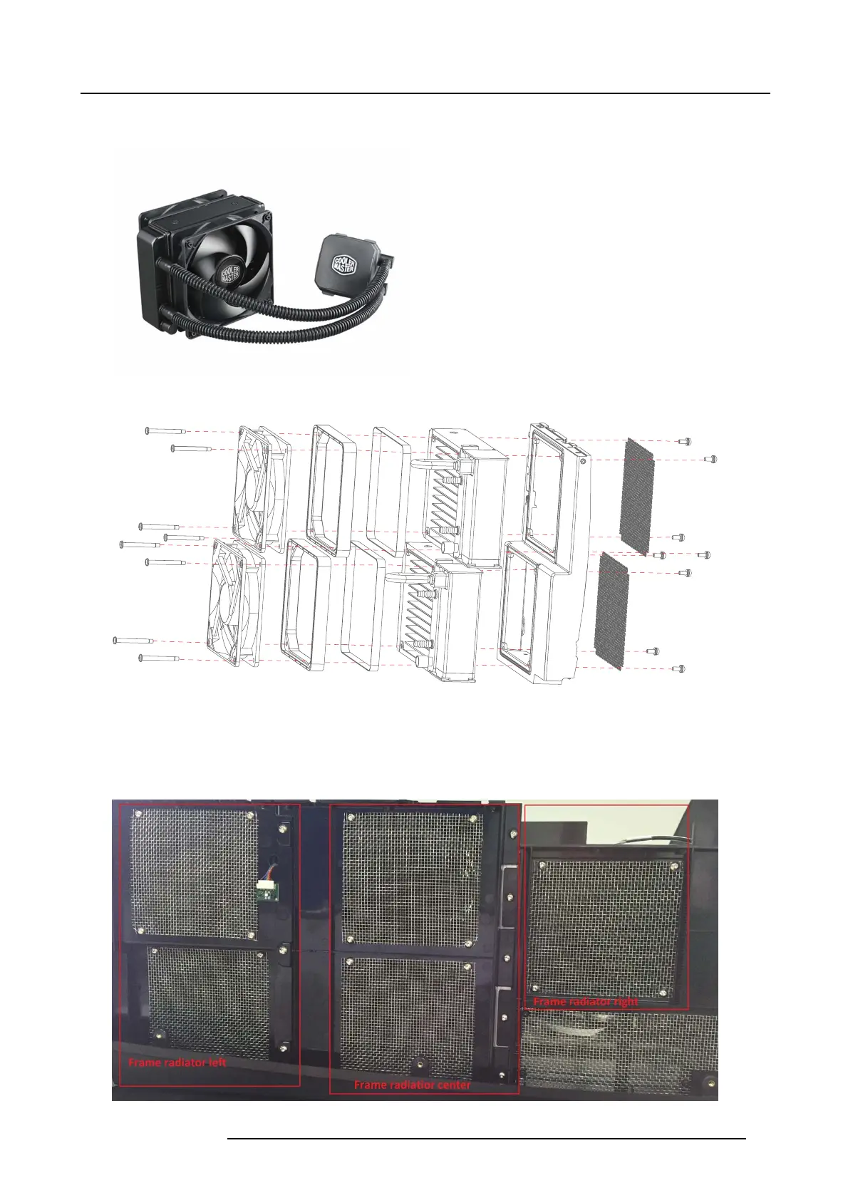
Image 20-31
Complete cooler assembly.
Image 20-32
Exploded view of the fan and radiator assembly
For illustration purposes the in the service m anual, the complete inlet cooling system has been split in three fram es/sec tions:
1. Frame radiator left (Coo ling of Left Laser Clus ter)
2. Frame radiator center (Cooling o f Right Las er cluster
3. Frame radiator right (Cooling of DMD)
Image 20-33
723–0016 F90 01/12/2017 97