3-93
Confidential
8.36 Modem PCB ASSY/Modem Flat Cable
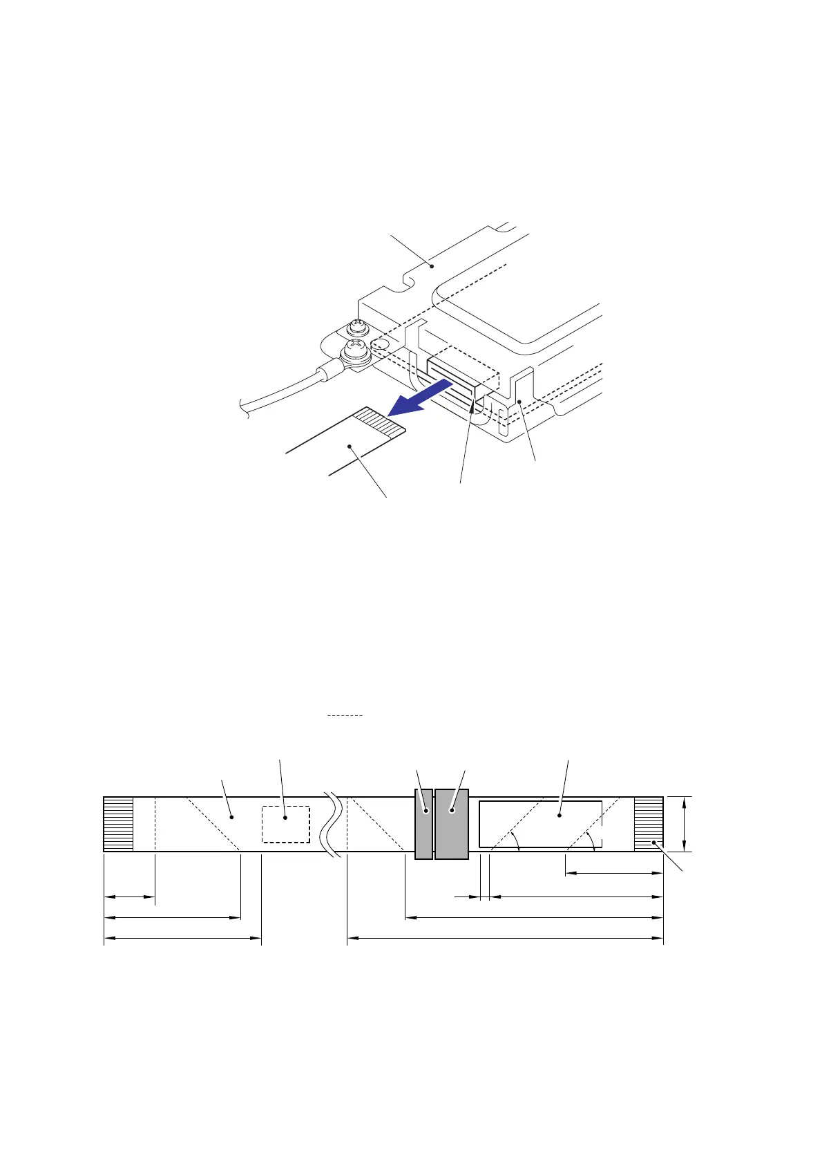
(1) Disconnect the Flat cable (CN1) from the Modem PCB ASSY.
Fig. 3-120
(2) Remove the two Flat cable sponges from the Flat cable.
(3) Remove the two Flat cores from the Flat cable.
Fig. 3-121
Modem PCB ASSY
CN1
Flat cable
Modem shield plate
Flat cable
Flat core (large)
Flat core (small)
Fold up FFC along with the dotted line
45°
45°
15±1 mm
68±1 mm
90±2 mm
192±1 mm
167±1 mm
5±1 mm
63±1 mm
28±1 mm
16 mm
<Main PCB ASSY side> <Modem PCB ASSY side>
Flat cable sponge 3
Flat cable sponge 2
(Attach it to the side of the terminal.)
(Attach it to the back side
of the terminal.)
Ter mi n al
side

 Loading...