TYPICAL PAGE - B
Section Title
Cable, Hose,
and
Wire
Rou
1n9
Route
all
hoses, control cables, and wiring
through a protective
sleeve or conduit into
the
boat and through the grommet.
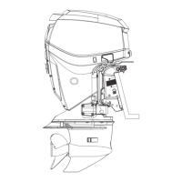
Refer to the
following diagram to ensure proper
positioning of rigging components
in
grommet.
1. Fuel supply hose
2.
Oil return hose
3.
Oil supply hose
4. Battery cables
5.
Ma
in
wire
harness (MWS)
6. Throttle cable
7.
Shift cable
8.
Oil tank sending unit harness
9. Water pressure hose
10.
Accessory charge wire
Model specific
illustrations
designated with
image captions
000084
Connect outboard main wire harness to boat
wire
harness.
Before installing
electrical connectors, check
the
seal is
in
place. Clean
Off
!!l!
d
!
irt
!
fr
~
o
!
m
~!!
nectors. Apply a light coat of
to
the
seal. Push connectors
latched.
1.
Seal
INTRODUCTION
TYPICAL
PAGE - B
a water pressure gauge
is
to
be
used, install the
water pressure hose fitting
in
the
cylinder block.
Use Pipe Sealant with Teflon
(PIN
910048)
on
the
threads of the hose fitting. Refer
to
installati
on
instructions supplied with gauge.
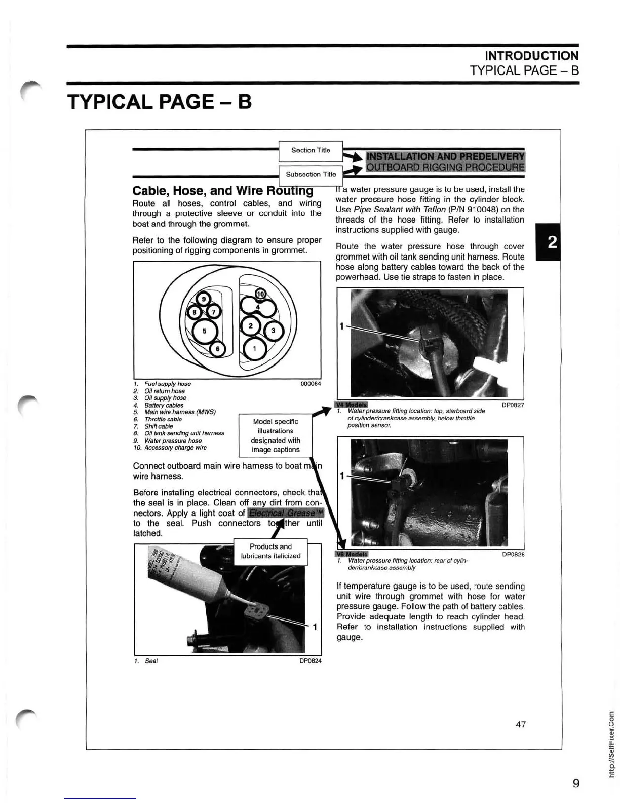
Route the water pressure hose through cover
grommet with oil tank sending unit harness.
Route
hose along battery cables toward the back of
the
powerhead. Use tie straps
to
fasten
in
place.
pressure fitting l
oca
t
io
n: top, sta
rb
oa
rd
side
of cylinder/crankcase assembl
y,
below t
hr
ottle
p
os
iti
on
sen
so
r.
If temperature gauge
is
to
be
used,
route
sending
unit wire through grommet
with
hose for
wa
t
er
pressure gauge. Follow the
path
of
battery cables.
Provide adequate length to
reach
cylinder head.
Refer to installation instructions
supplied
with
gauge.
47
9