INSTALLATION
AND
PREDELIVERY
BOAT RIGGING
BOAT RIGGING
Remote
Controls
Control
Selection
6 WARNING 6
The remote control used
must
have start-
in-gear prevention. This feature can pre-
vent
injuries
resulting
from
unexpected
boat
movement
when the
outboard
starts.
Remote
control styles and applications are
described
in
the Evinrude/Johnson Genuine Parts
and Accessories Catalog.
Plan the installation of
all remote controls carefully. Read the outboard's
Operator's Guide
and
the remote control's installa-
tion instructions prior to installation.
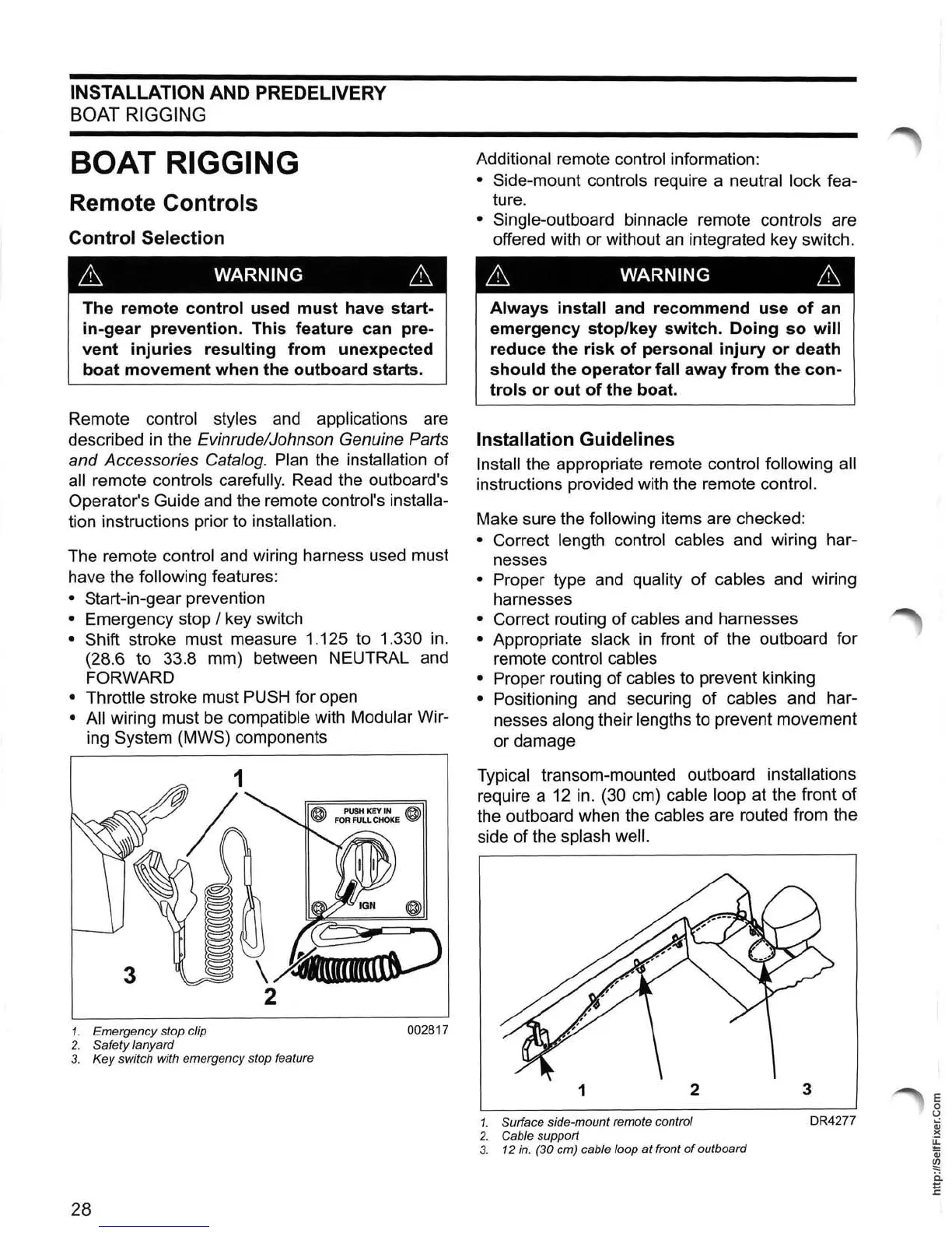
The remote control and wiring harness used must
have the
following features:
• Start-in-gear prevention
• Emergency stop / key switch
• Shift stroke must measure 1.125 to 1.330
in.
(28.6 to 33.8 mm) between NEUTRAL and
FORWARD
• Throttle
stroke must
PUSH
for open
• All wiring must
be
compatible with Modular Wir-
ing System (MWS) components
1. Emergency stop clip
002817
2.
Saf
ety lanyard
3.
Key switch with emergency stop feature
28
Additional remote control information:
• Side-mount controls require a neutral lock fea-
ture.
• Single-outboard binnacle remote controls are
offered with or without
an
integrated key switch.
6 WARNING 6
Always install and recommend
use
of
an
emergency
stop/key
switch.
Doing
so
will
reduce the
risk
of
personal
injury
or
death
should
the
operator
fall away
from
the
con-
trols
or
out
of
the boat.
Installation Guidelines
Install the appropriate remote control following all
instructions provided with the remote control.
Make sure the following items are checked:
• Correct length control cables and wiring har-
nesses
• Proper type and quality of cables and wiring
harnesses
• Correct routing of cables and harnesses
• Appropriate slack
in
front of the outboard for
remote
control cables
• Proper
routing of cables to prevent kinking
• Positioning and securing of cables and har-
nesses
along their lengths to prevent movement
or damage
Typical transom-mounted outboard installations
require a
12
in. (30 cm) cable loop at the front of
the outboard when the
cables are routed from the
side of the
splash well.
1
2
3
1. Surface side-mount remote control
DR4277
2.
Cable support
3. 12 in. (30 cm) cable loop
at
front
of
outboard
E
o
U
Qj
)(
~
Qj
~
ii
E