ELECTRICAL
ELECTRIC STARTER SYSTEM
Inspection
Ignition Switch (Remote Models)
Disconnect the ignition switch from remote control
wiring harness.
Check continuity between switch
terminals at the
key positions shown:
Key Switch Terminals
Position
M M
B A S C
OFF
ON
~ ~
START
~
~
~
PUSH
~
~ ~
~
-
0---0
:
Continuity
If out of specification, replace the ignition switch.
Starter Button (Tiller Models)
Disconnect the starter button lead wire.
Check continuity between the wiring
leads under
the conditions shown:
Tester probe connection
Continuity
Probe Other Probe
Starter
button
No
not
depressed
White/Red Brown
Starter
button
Yes
depressed
If out of specification, replace the starter button.
78
Neutral Switch
Disconnect neutral switch lead wire.
Check continuity between
lead wires while operat-
ing the shift
lever of remote control.
Shift
position
Continuity
Neutral Yes
Forward No
Reverse No
If out of specification:
• Check switch position adjustment.
• Replace neutral switch.
IMPORTANT: After installing neutral switch,
check for proper function.
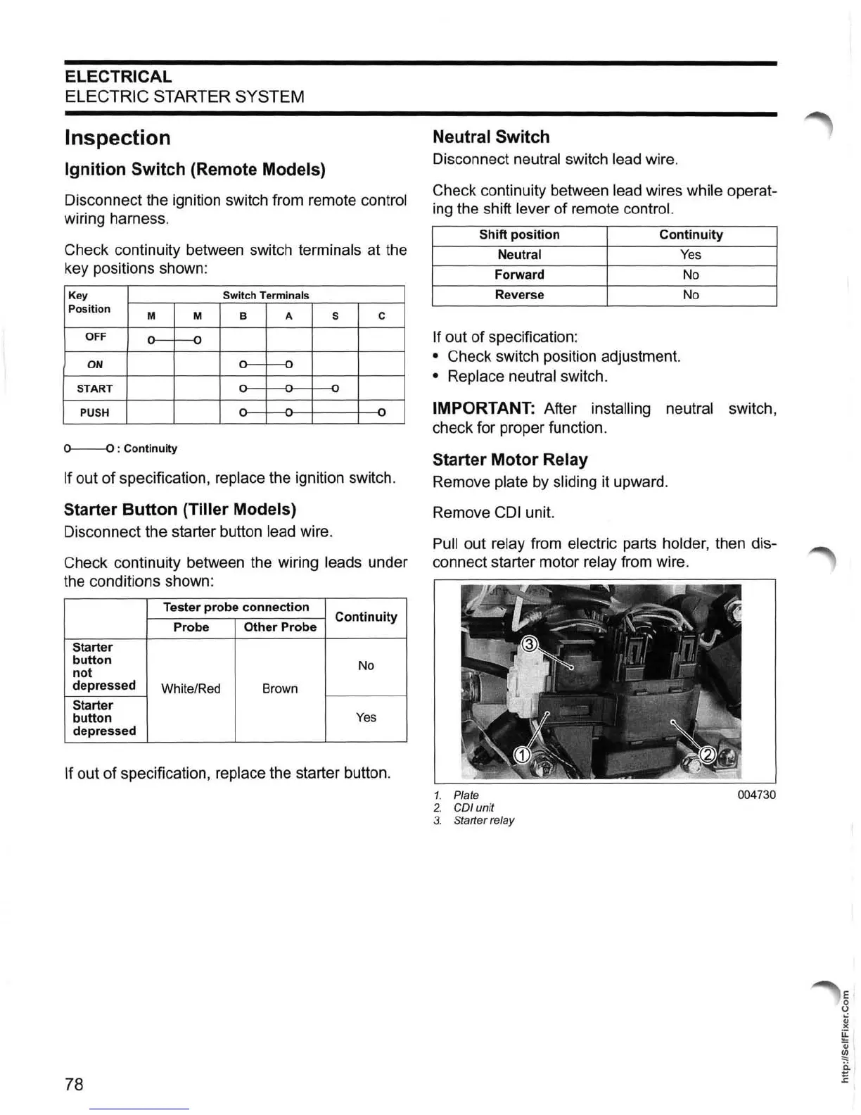
Starter Motor Relay
Remove plate by sliding it upward.
Remove
CDI
unit.
Pull out relay from electric parts holder, then dis-
connect starter motor
relay from wire.
1. Plate
004730
2.
COl unit
3. Starter relay
E
o
o
~
><
u:
....
,
Oi
l
~
C.
E