TYPICAL PAGE - D
Two pulse hoses connect the pump to pulse fit-
tings
on
the front of the cylinder/crankcase.
• V4 Models - cylinders 1 and 3
• V6 Models - cylinders 1 and 4
r-Manifold
distributes the oil sup-
oil
lift pump. A pressure-sensing
oil injection pressure.
Oil
Injector-Manifold
Cpal.D.CI.D.CILDn~----,
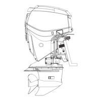
• 40 V oil injector Cross references
• Oil distribution manifold direct readers to
related topics
• Oil pressure switch
• Pressure regulator (oil return hose)
• Oil distribution hoses
• Oil to fuel check valve
3
3
2
1
4
TYPICAL
000722
1. Oil injector
2.
Oil distribution manifold
3.
Oil distribution hoses
4.
Oil
to
fuel check valve
INTRODUCTION
TYPICAL PAGE - 0
OILING SYSTEM
COMPONENTS
Oil Pressure Switch
The oil pressure switch
is
located
in
the oil injec-
tor-manifold and reacts
to
changes
in
oil manifold
pressure. The
EMM
supplies and monitors electri-
cal
current to the switch.
components
numbered
to
The switch opens or correspond
to
oil manifold pressures: image
53 psi (365 kPa) (nominal) to close
43 psi (296
kPa) (nominal)
to
reopen
Service Code 38
A faulty electrical circuit or
an
inoperative pres-
sure switch activates service code
38
(no oil sen-
sor feedback or
lack of oil pressure) and the EMM:
Service Code 39
quicker reference
when thumbing
through
manual
If
no oil pressure
is
detected during startup, the
EMM
initiates
an
oil injector "recovery mode"
to
pressur
iz
e the system. If inadequate oil pressure
is
still detected after the recovery mode
is
com-
pleted, the EMM:
Activates the System Check "NO OIL" light
Stores a service code
Initiates S.L.O.w.
209
11
E
o
o
..:
OJ
)(
~
Qj
<II
::::
ii
t:
.t::