VPSB-DC and VPSB-DC-E
178 / 234 H172203_1_001
15.5.2 Diagnostic and Troubleshooting
During normal operation all important signals and supplies are supervised. In case of a fatal
hardware failure the board will go to a safe state (e.g. shut down of the power conversion
stages). This is implemented with a board watchdog system. Board level trouble shooting
must be done in the factory.
In case of failures, always check the LEDs on the VPSB-DC(-E) front panel:
• Red ERROR LED must be off.
• Green READY LED and POWER LED must be on. If the POWER LED is off, three
serviceable fuses for the VPSB-DC, and five for the VPSB-DC-E can be checked, see
Serviceable Fuses [}178].
• If a VTA is connected, the corresponding green LED must be on.
• If the output on a channel is on (e.g. during temperature regulation) the corresponding
yellow LED (VT PWR 1 or VT PWR 2) must be on. If not, check cables, connectors and
firmware on connected devices.
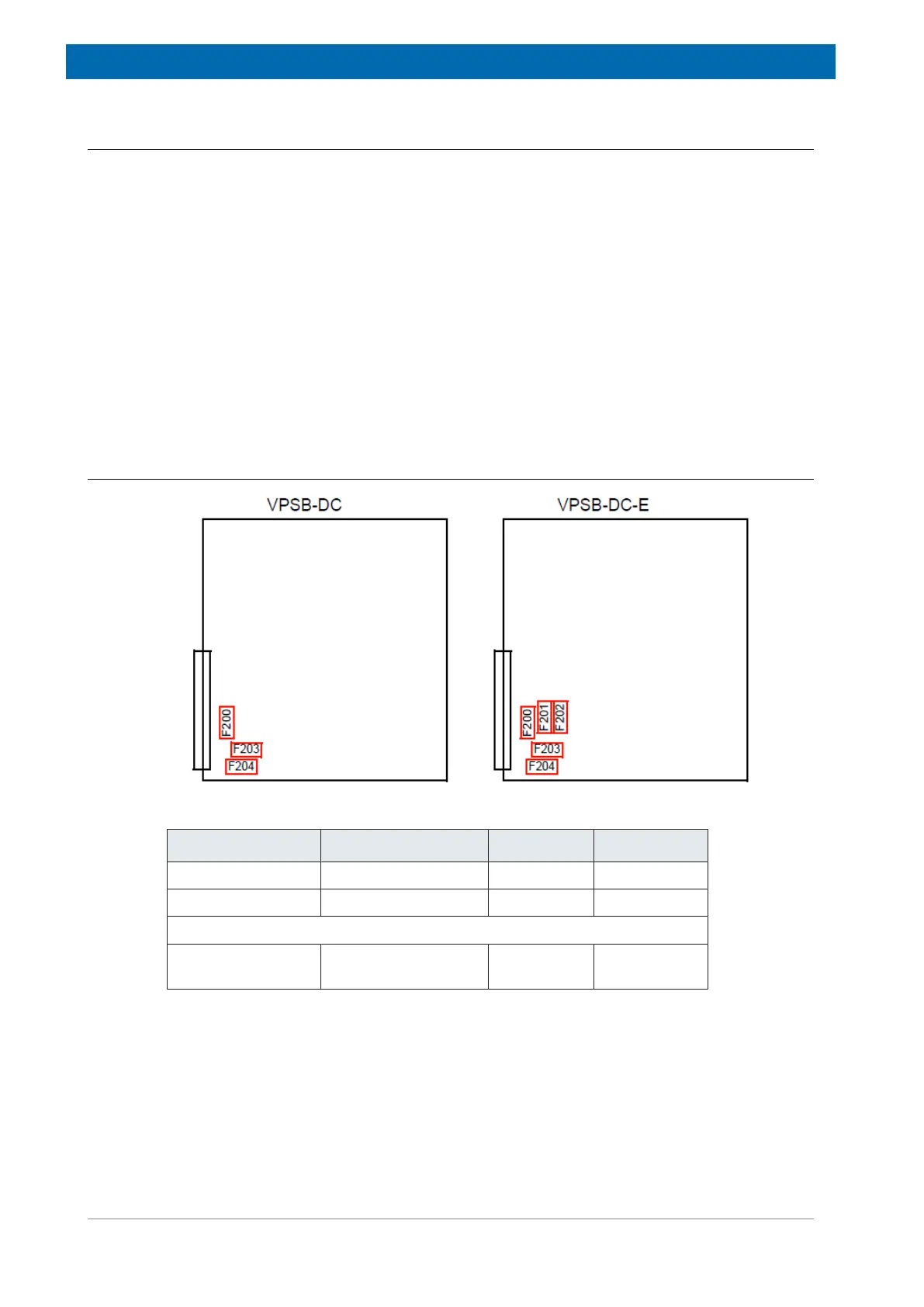
15.5.2.1 Serviceable Fuses
Figure15.6: VPSB-DC(-E) Fuse Placement
Supply Fuse Part No. Value
+24V Supply F200 1802109 3.15 AT H
+/-24V power input F203, F204 49216 8.0 AT H
VPSB-DC E only:
+/-24V extension
board power input
F201, F202 49216 8.0 AT H
Table15.9: Fuses on VPSB-DC(-E)