EasyManuals Logo
Home>Bruker>Chassis>NMR BSMS System

Bruker NMR BSMS System User Manual

Bruker NMR BSMS System
234 pages
To Next Page IconTo Next Page
To Previous Page IconTo Previous Page
Page #175 background imageLoading...
Page #175 background image
VPSB-DC and VPSB-DC-E
H172203_1_001 175 / 234
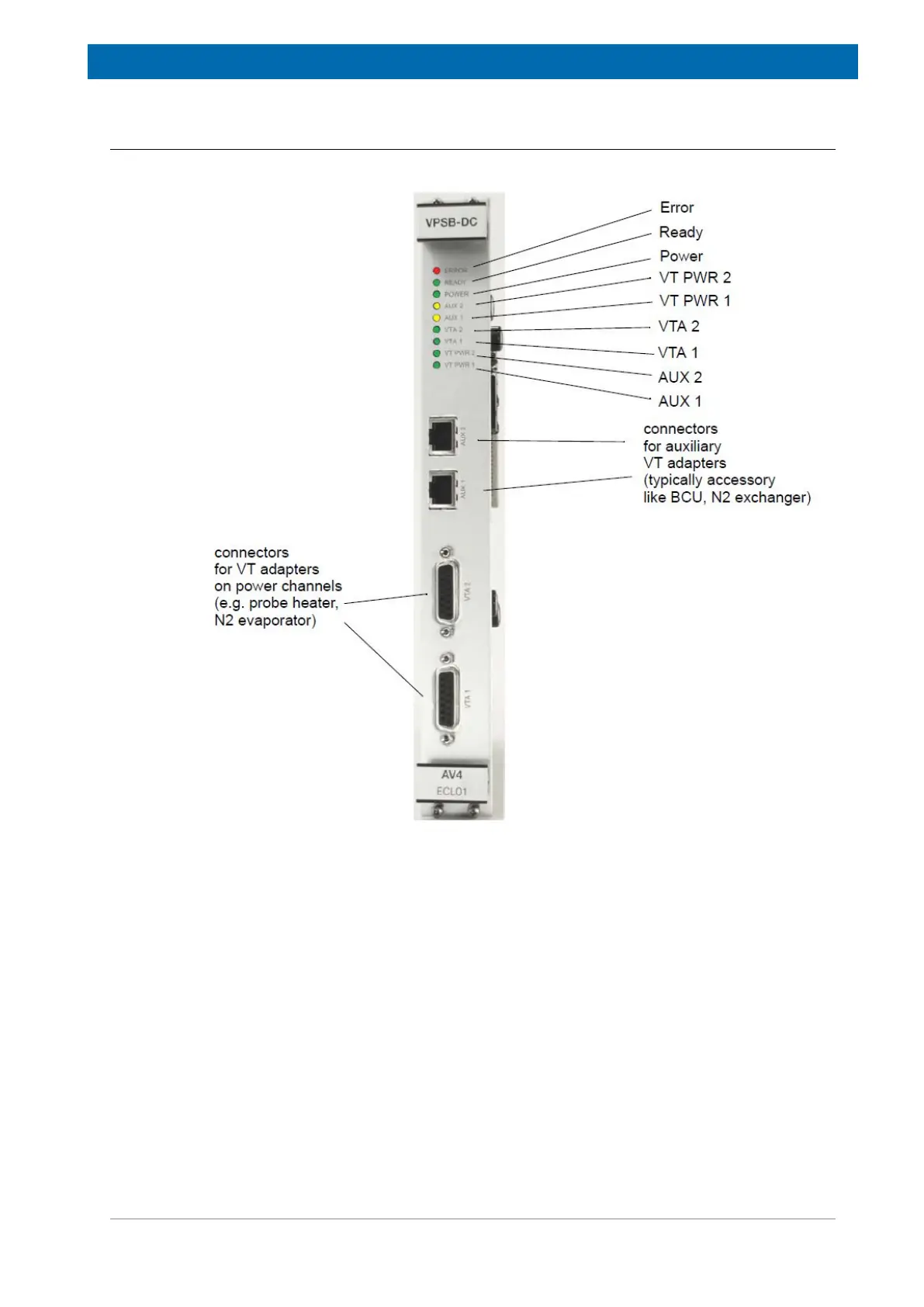
15.4.6 Front Panel - Connectors and LED‘s
All interfaces for both the VPSB-DC and the VPSB-DC-E are the same.
Figure15.4: Front View of a VPSB-DC
Error LED
This LED is lit after power ON. It turns off as soon as the VPSB-DC(-E) is initialized (i.e. the
FPGA has loaded its configuration from the flash memory and the communication with the
ELCB is established).
Later on, an active Error LED indicates that an error has occurred (e. g. short circuit,
watchdog event,...) and that in consequence the connected VTAs and the power outputs are
switched off.

Table of Contents

Questions and Answers:

Question and Answer IconNeed help?

Do you have a question about the Bruker NMR BSMS System and is the answer not in the manual?

Bruker NMR BSMS System Specifications

General IconGeneral
BrandBruker
ModelNMR BSMS System
CategoryChassis
LanguageEnglish