Chassis (Mainframe)
H172203_1_001 39 / 234
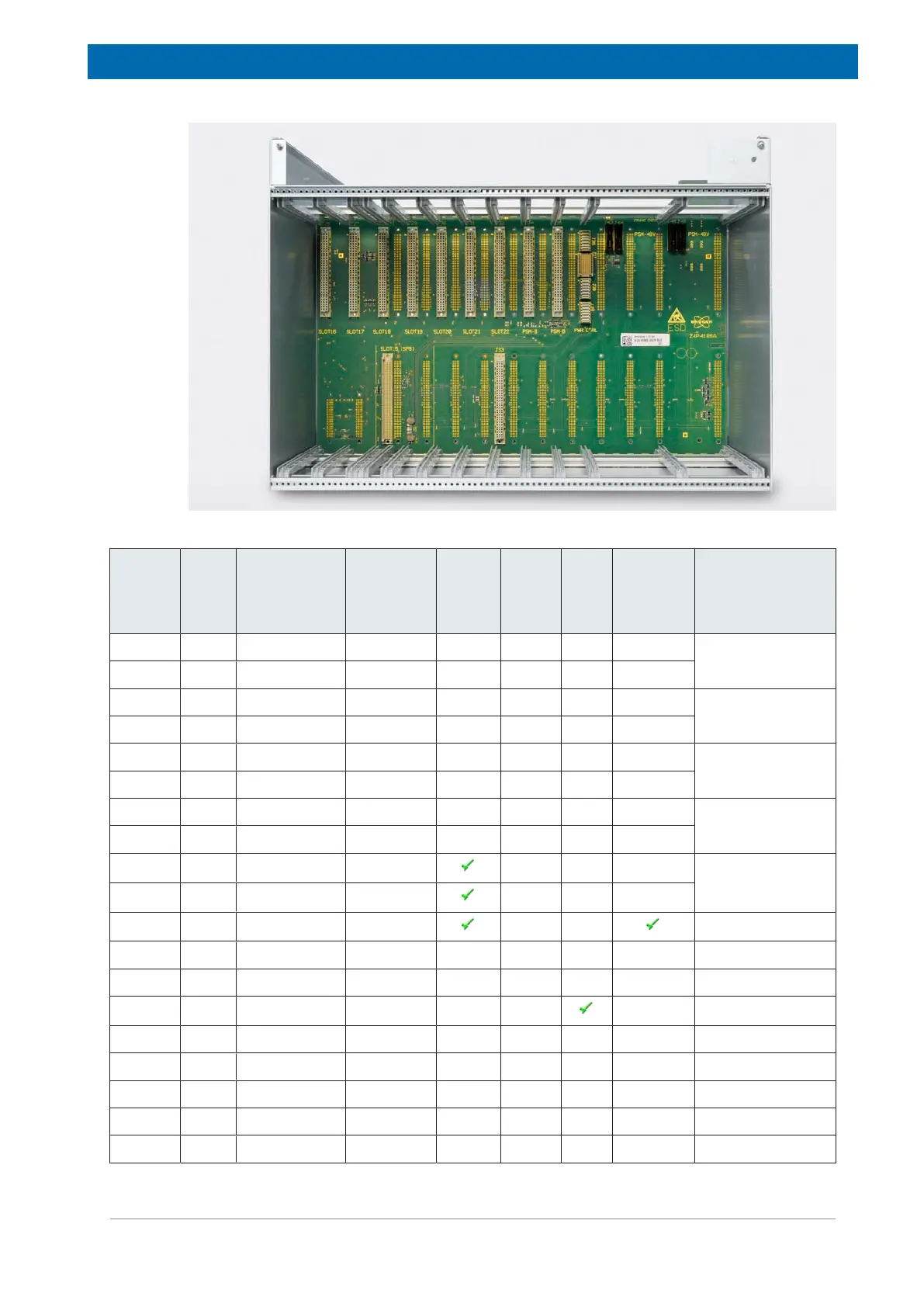
Figure5.2: BSMS Chassis Rear View including Fan Tray
Slot Slot
ID
SSRB
Address
I2C Bus
No.
H0
Curre
nt
Fused
24V
Secti
on
He
Sup
ply
H0
Supply
Typical Unit
Slot 0 0 0 7 1
AV4 GAB/2 [X]
Slot 1 1 1 7 1
Slot 2 2 2 7 1
AV4 GAB/2 [Y]
Slot 3 3 3 7 2
Slot 4 4 4 7 2 AV4 GAB/2 [Z]
Slot 5 5 5 7 3
Slot 6 6 6 7 3 SCB20 [B]
Slot 7 7 7 7 3
Slot 8 8 8 1 4 SCB20 [A]
Slot 9 9 9 1 4
Slot 10 10 10 Master Lock ELCB
Slot 11 11 11 - Lock L-TRX
Slot 12 12 12 - - L-19F
Slot 15 15 15 1 SPB SPB(-E)
Slot 16 16 16 2 AUX -
Slot 17 17 17 2 AUX AV4 VPSB-DC
Slot 18 18 18 2 AUX -
Slot 19 19 19 2 AUX -
Slot 20 20 20 2 AUX AV4 VPSB-DC(-E)