Power Supply Modules
H172203_1_001 51 / 234
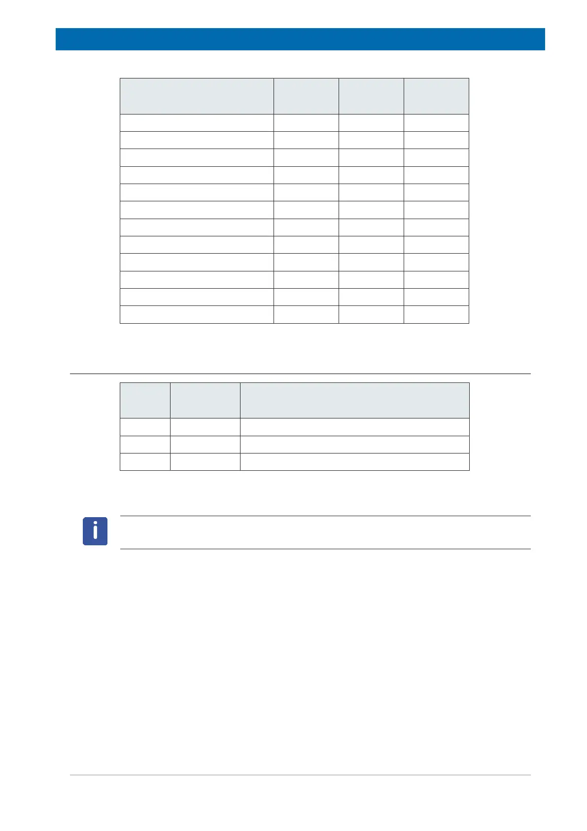
Supply Fuse Part No. Value
(IEC)
+24V AUX Slot 16 .. 24 F1 49216 8.0 AT H
+24V Section 1Slot 0 .. 2 F2 49216 8.0 AT H
-24V Section 1Slot 0 .. 2 F3 49216 8.0 AT H
+24V Section 2Slot 3 .. 4 F4 49216 8.0 AT H
-24V Section 2Slot 3 .. 4 F5 49216 8.0 AT H
+24V Lock Slot 10 .. 12 F6 1802109 3.15 AT H
+24V SPB Slot 15 F7 49216 8.0 AT H
+24V Section 3Slot 5.. 7 F8 49216 8.0 AT H
-24V Section 3Slot 5.. 7 F9 49216 8.0 AT H
+24V Section 4Slot 8.. 9 F10 49216 8.0 AT H
-24V Section 4Slot 8.. 9 F11 49216 8.0 AT H
+24V Accessory Connector F12 1801717 6.3 AT H
Table7.2: Fuses PCTRL
7.3.4 Part Numbers
Type Bruker
Part No.
Description
AC/DC Z149850 AV4 PSM-48V POWER SUPPLY MODULE
DC/DC Z150090 AV4 PSM-B POWER SUPPLY
Ctrl Z150089 AV4 BSMS POWER CONTROL BOARD
Table7.3: BSMS Power Supply Part Numbers
BSMS/2 chassis PSM and PSB are not compatible to the AV4 BSMS chassis!