VTA
192 / 234 H172203_1_001
16.5 Service
16.5.1 VTA Service Web
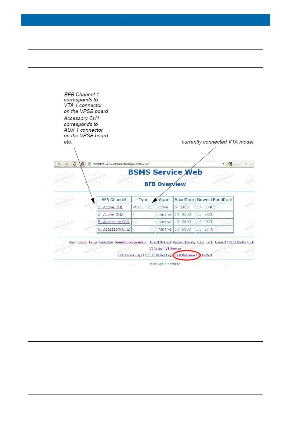
There is no particular web site for each connected VTA, but there is a common page listing
all VTA or other devices connected to one of the peripheral bus (BFB, Bruker Field Bus)
connectors:
Figure16.5: Overview of VTAs Connected to the BFB Peripheral Bus
16.5.2 Diagnostic and Troubleshooting
The device state is displayed using the 5 LED. See Figure 16.4 [} 191] for a detailed
description.
In addition, on-board diagnosis data or failure events are sent to the ELCB immediately and
displayed within TopSpin GUI or Logfile.
16.6 System Requirements
See Minimal requirements for all configurations in the chapter Basic BSVT Configuration
[}124].