VTA
188 / 234 H172203_1_001
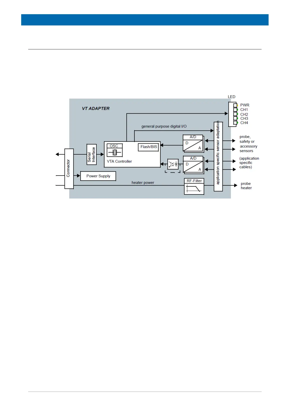
16.4 System Architecture / Overview
The primary function of the VTA is to adapt the various sensors and signals of probe and
chiller devices to the common interface of the BSMS integrated VT system.
Inside the VTA a common basic infrastructure for configuration, communication and board
identification (BIS) is available. Depending on the specific function these are complemented
by the appropriate number of ADC channels, galvanic isolation or sensor excitation signals.
Some VTA (e.g. for connecting a BCU) are equipped with solid-state switches.
Figure16.2: Block Diagram of the VT Adapter
Thermocouple Adaptation (VTA TC-2T, TC-2E)
The thermocouple signal from the probe is fed into the VTA where the cold-junction
compensation and signal conversion is done. Simultaneous measurements of sensor
temperature and cold-junction temperature leads to precise results. The heater current is fed
through the VTA for RF filtering before entering the probe. A dedicated ADC channel is used
for measuring the safety temperature sensor that is mounted on the heater to prevent
overheating. Broken, ground-shorted or disconnected sensor lines are detected for safety
and diagnostic reasons.
Mainly for Solids NMR and high temperature applications there VTA offers two thermocouple
connectors. VTAs are fully operable with only one sensor connected. The open sensor line
will be ignored and the VTA behaves like a single sensor type.
BTO2000 Adaptation (VTA BTO)
The cold-junction compensated signal from the BTO2000 is fed into the VTA where the signal
conversion is done. The VTA BTO provides the power supply for the thermal oven and
electronics of the BTO2000. Apart from that the device provides the same functionality as the
TC-2T variant.