ELCB
H172203_1_001 57 / 234
8.4.1 Protection
The power amplifier providing the lock current for the H0 coil is protected against short
circuits (limiting the output current) and over temperature.
8.4.2 Lock Software Architecture
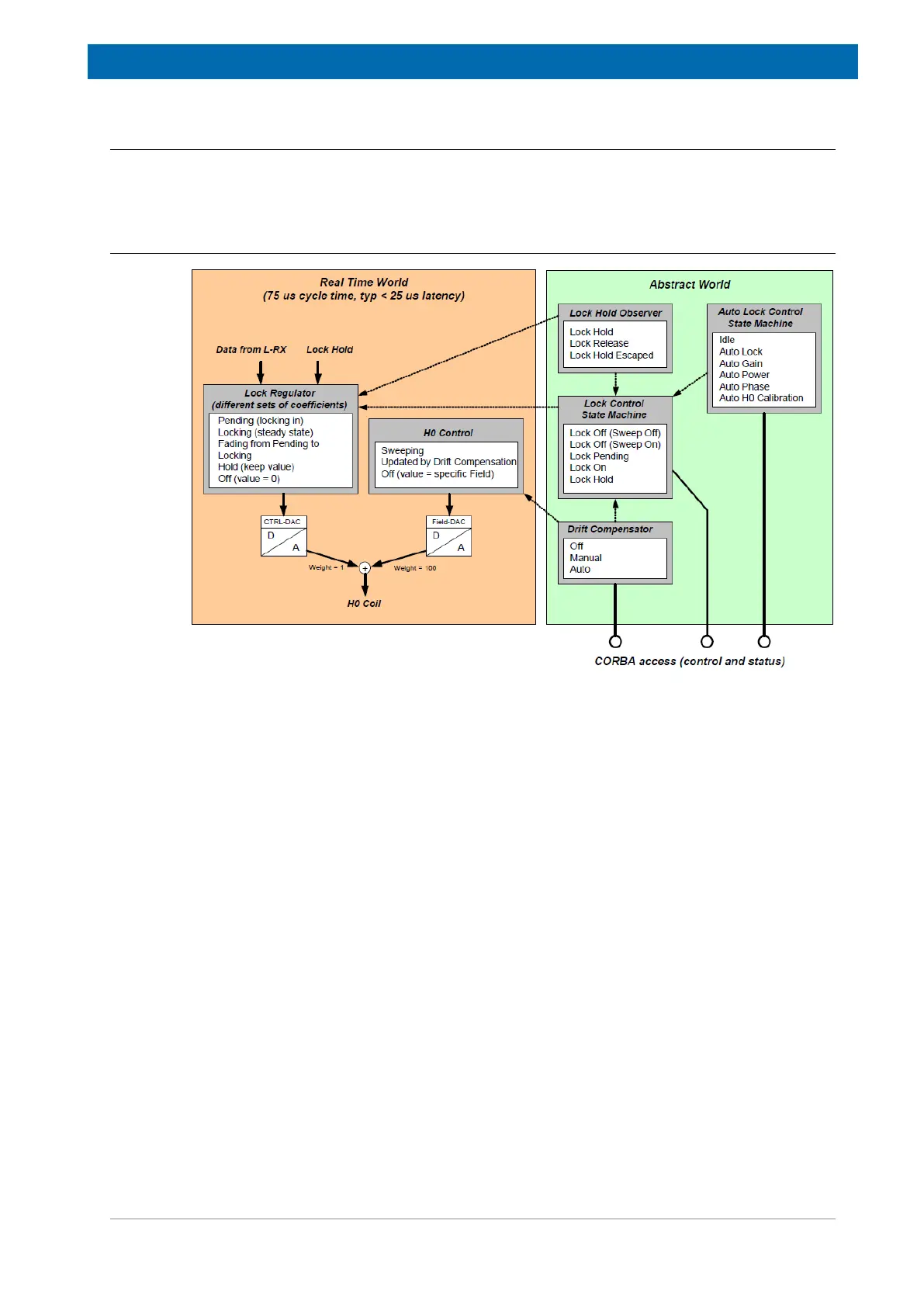
Figure8.3: Abstract Control Domain and Real Time Domain
One part of the Lock software runs in „real time“ mode: An interrupt service routine is called
every 75 microseconds. This routine reads the Lock receiver data and evaluates the
corresponding Ctrl-DAC and Field-DAC values, which are applied by the Control FPGA to the
hardware. The typical delay time from arrival of the receiver data to the completion of the
DAC write cycle is less than 25 micro seconds.
On the other hand, there is a more abstract part, modelling the Lock behavior and controlling
higher level functions, e. g. locking in, selecting the appropriate set of Regulator Coefficients,
compensating the drift and so on. This part of the software is connected with the CORBA
interface - it handles requests from the TopSpin application and notifies about state changes
(e. g. Lock Hold). It is non-real time and may react with a delay of several milliseconds.
The Lock Hold signal affects directly the regulator, which guarantees extremely short reaction
times. An external Lock Hold Observer examines every 20 milliseconds the Lock Hold state.
If the regulator runs in Lock Hold mode or if a short Lock Hold pulse has been active in the
mean time (Lock Hold Escaped) then the Lock Hold Observer updates the Lock Control State
Machine and notifies the registered clients - even the shortest Lock Hold pulses are indicated
on the keyboard (if connected) and in the TopSpin application.