SCB20
H172203_1_001 73 / 234
9.3.2 Configuration for BOSS2, 3 and WB
For the operation of a BOSS2, BOSS3 or BOSS-WB Shim System two SCB20 Units are
required. Current „plug“-type Shim Systems can be directly connected to the SCB20, using
the according Shim cables.
9.4 System Architecture/Overview
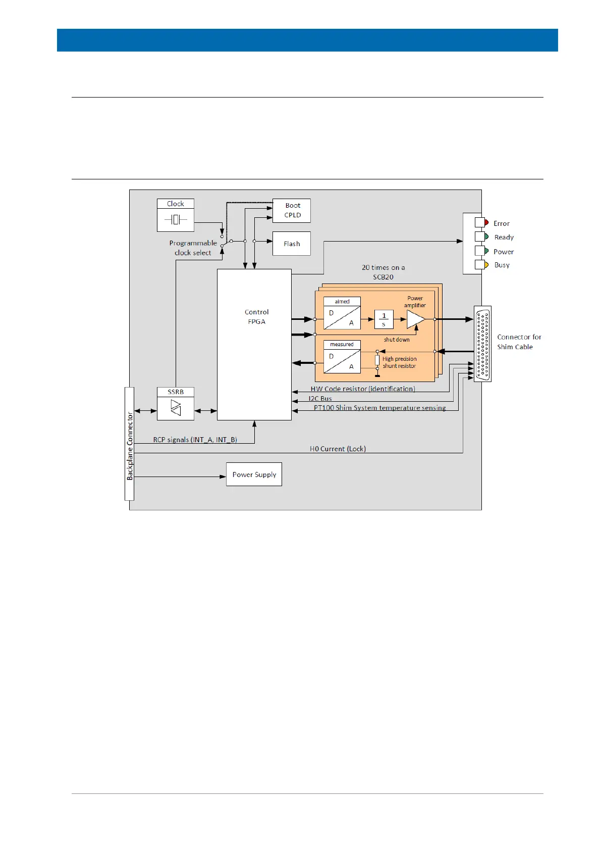
Figure9.2: Block Diagram of the SCB20 Shim Current Board
The SCB20 is a SSRB slave and controlled by the ELCB, which is the AV4 BSMS controller/
coordinator. In addition to the SSRB and power supply, there are the synchronization signals
for RCP Shimming (INT_A, INT_B) that are provided by the AV4 GTU and that are routed
across the ELCB. Also, the H0 current for Locking is provided by the ELCB - it is routed by
the shim cable to the Shim System, which contains also the H0 coil for the lock.
In normal configuration the SCB20 uses a common 10MHz clock that is distributed by the
ELCB (this clock is typically generated by the AV4 reference board). It is possible to select
alternatively a local oscillator.
When the SCB20 is starting up, then the CPLD loads at first the current FPGA design from
the flash. It is therefore possible to upgrade SCB20 boards in the field (e. g. for new
features). The FPGA provides coordination/control of the hardware functions (e. g. controlling
the current source regulator loops, protection and real-time functions). As soon as the FPGA
is ready, the corresponding embedded software of the ELCB initializes the parameter settings
(e. g. values of the shim currents) and starts operation.
The yellow Busy light flashes whenever there is interaction with the ELCB - there is a task
running on the ELCB that periodically checks the connected SCB20 boards, which results in
a regular flashing of the Busy LED‘s.