ELCB
60 / 234 H172203_1_001
8.4.6 Calibration
It is user selectable whether the Lock adjusts the Field (default) or the Shift (optional) for
locking in by the Auto Lock procedure. The relation between the frequency and the field
depends on the Shim System (different for standard bore, wide bore and super wide bore
magnets), which is defined in the BOSS file. This value may deviate additionally between
different individuals of the same type.
In the Service Web there is a push button calibration of this relation. The calibration needs a
sample containing a lock relevant solvent.
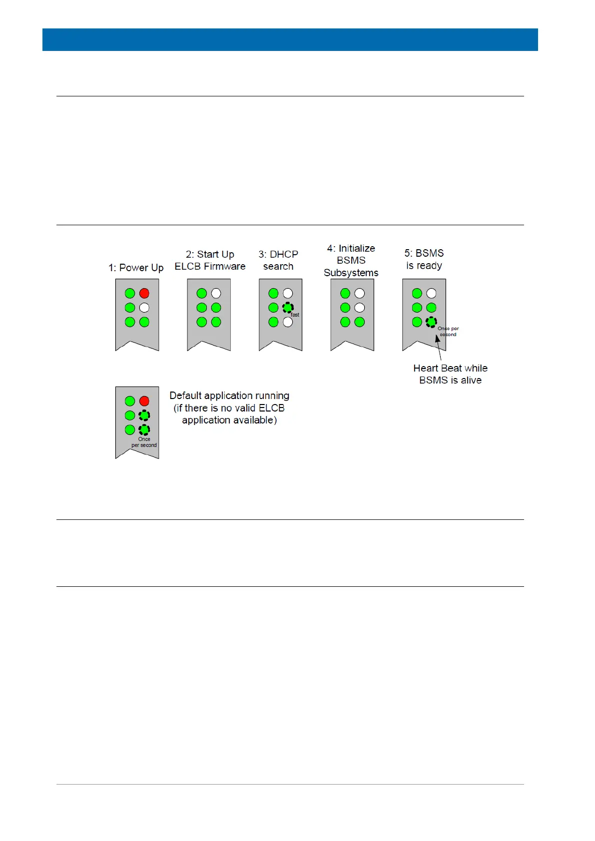
8.4.7 Front Panel - LED‘s during Start Up
Figure8.5: LED‘s Indicating Different States During Start Up
8.5 Bus Interface
Since the ELCB is the master of the AV4 BSMS, it controls the communication busses of the
backplane, the User Bus.
8.5.1 Front Connectors
An additional RJ45 connector provides the RCP inputs, according to the figure below. The
LED near the connector is active when a RCP signal is actually handled by the ELCB. Thus,
this LED serves for checking if the RCP pulse signals are available and if they are handled as
expected (e. g. if RCP handling is enabled for the specific signal). It is blinking e. g. during
Gradient experiments (Lock Hold) or RCP shimming (INT_A).