ELCB
56 / 234 H172203_1_001
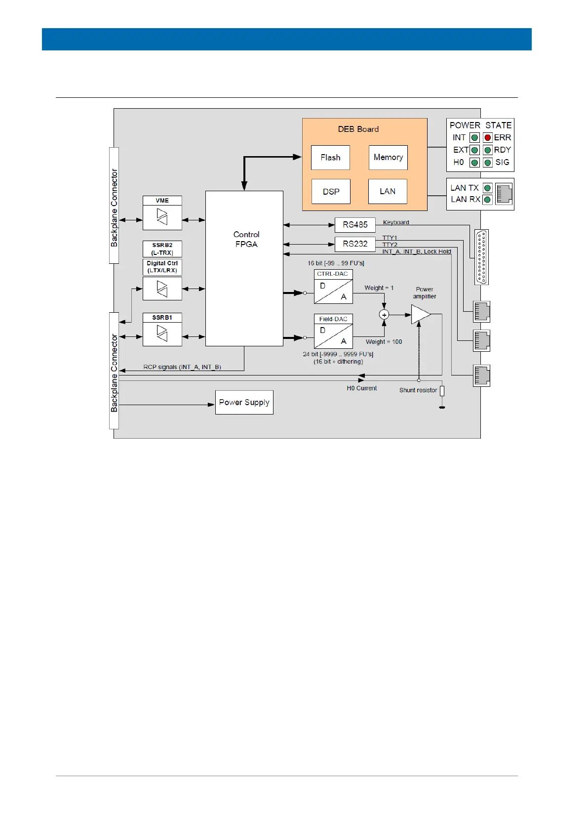
8.4 System Architecture/Overview
Figure8.2: Functional System Architecture
The processor board (DSP Ethernet Board DEB) is a separate board plugged onto the base
board. It contains a signal processor with memory, Flash and the electronics that provides
access to the ethernet.
A central control FPGA handles the access to the peripheral hardware - actual BSMS/2
boards (e. g. SCB20, GAB/2, SPB, VPSB, L-TRX) communicate over SSRB, whereas the
power supplies and fan are controlled over an I2C bus. There are three RJ45 connectors, two
of them are TTY ports, which provide control for SampleCase (and similar). and Real time
signals (INT_A and INT_B for RCP-Shimming, Lock Hold).