Power Supply Modules
52 / 234 H172203_1_001
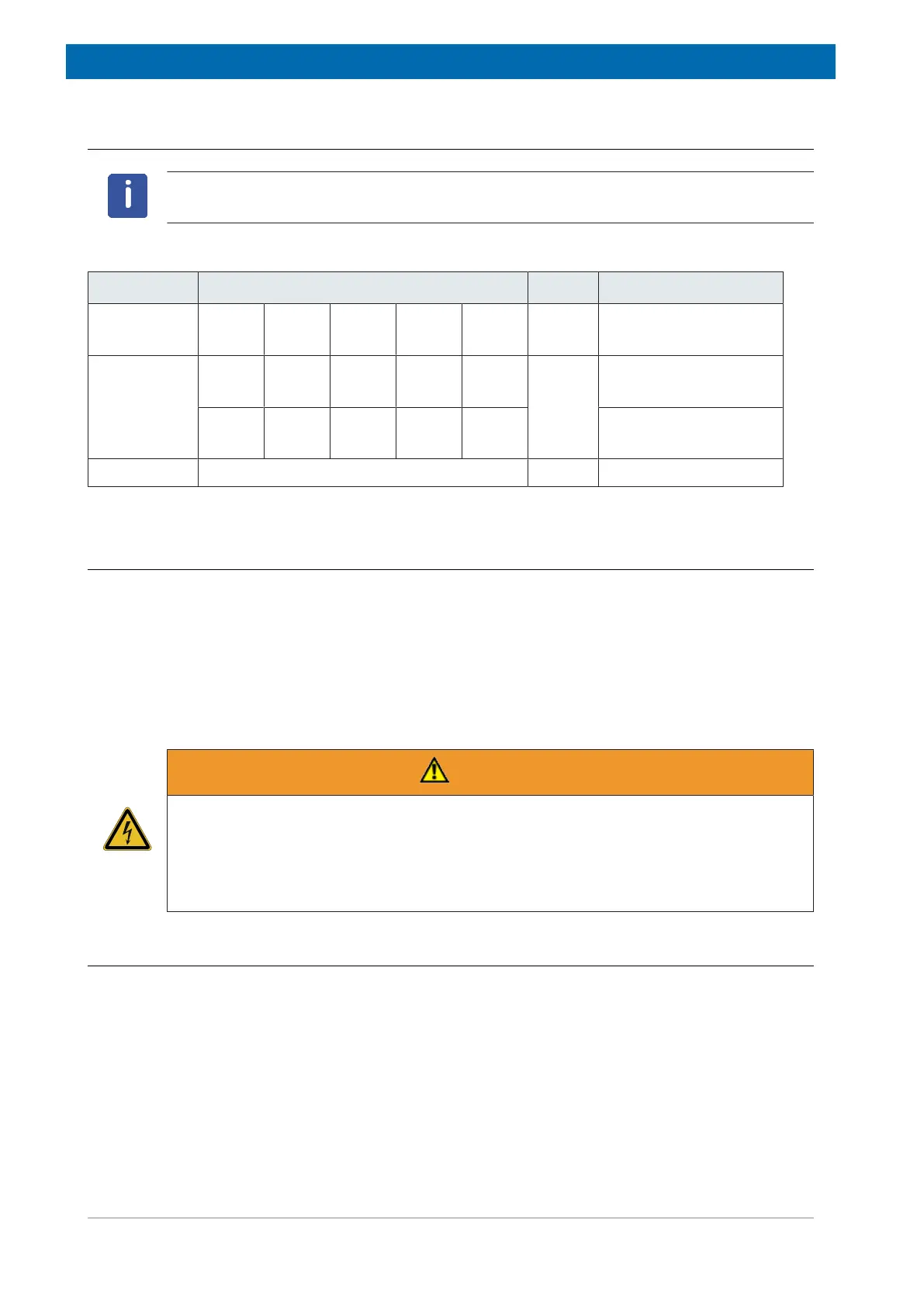
7.3.5 Technical Data (Summary)
Input specifications of AC/DC PSM see Connection Values [}219].
Short name Output Voltage / Current Power Load
PSM-48V +24 V
25 A
-24 V
25 A
1200 W PSM-B, PCTRL
VPSB-DC (-E)
PSM-B +12 V
5.5 A
+5 V
11 A
+3.6 V
11 A
+15 V
1 A
-15 V
1 A
230 W BSMS units, Fan Tray
+29.5 V
0.3 A
-29.5 V
0.3 A
+3 0V
0.35 A
H0-Current (ELCB), He-
Sensor (SPB)
PCTRL +/- 24 V switched and fused BSMS units
Table7.4: Power Supply Module Output Specification
7.4 Troubleshooting
Some PSM contain fuses accessible for Bruker service personnel. See description of the
individual PSM. Other than that there are no serviceable parts.
If fuses need to be replaced, contact Bruker service.
Detected failures are reported with event messages. Event messages are displayed on the
TopSpin screen and can be viewed on the ServiceWeb pages General information on trouble
shooting, error handling and failure reporting is available in chapter Troubleshooting [}213].
WARNING
Risk to life due to electrical shock
The device contains a high-voltage section. A life threatening shock may result when the
housing is open during operation.
u Only qualified personnel should open the housing.
u Disconnect the device from the electrical power supply before opening the device.
7.4.1 Diagnostics
The supply status is indicated either with one POWER LED for all output voltages or one LED
per output voltage.
PSM with I2C bus have internal diagnostics. The overall status is supervised by the BSMS
Software. Other diagnostics (voltage, current, temperature etc.) are available on the Service
Web page, depending on the capabilities of the individual PSM.