VTA
H172203_1_001 191 / 234
LED‘s CH1/2/3/4 and VT POWER
The LEDs on the VT adapters indicate the status of the adapters (connected, initialized). The
indicated channel number (CH1, CH2, CH3, CH4) corresponds to the number which is
displayed in the BSMS Service Web or on the vtudisp in TopSpin.
VT adapters can be connected or disconnected at any time. The temperature control will go
to OFF state if disconnected
In general, the
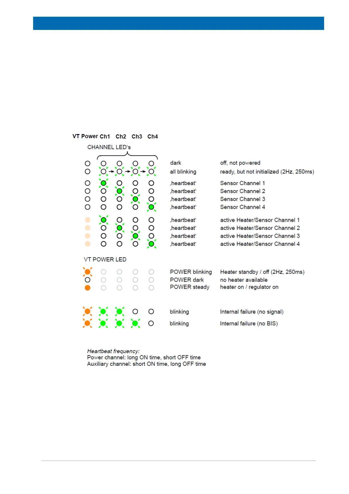
• Green LED indicates the channel number and state.
• Amber LED indicates the heater status (power on, standby, on state).
Figure16.4: LED Code on VT Adapters
Bus Interface
VT Adapters are connected to the VPSB or SPB-E. These boards provide the necessary
power supply and data interface signals.