CAPINTEC, INC. CAPRAC
®
-t
April 2021 SYSTEM SETUP 4-3
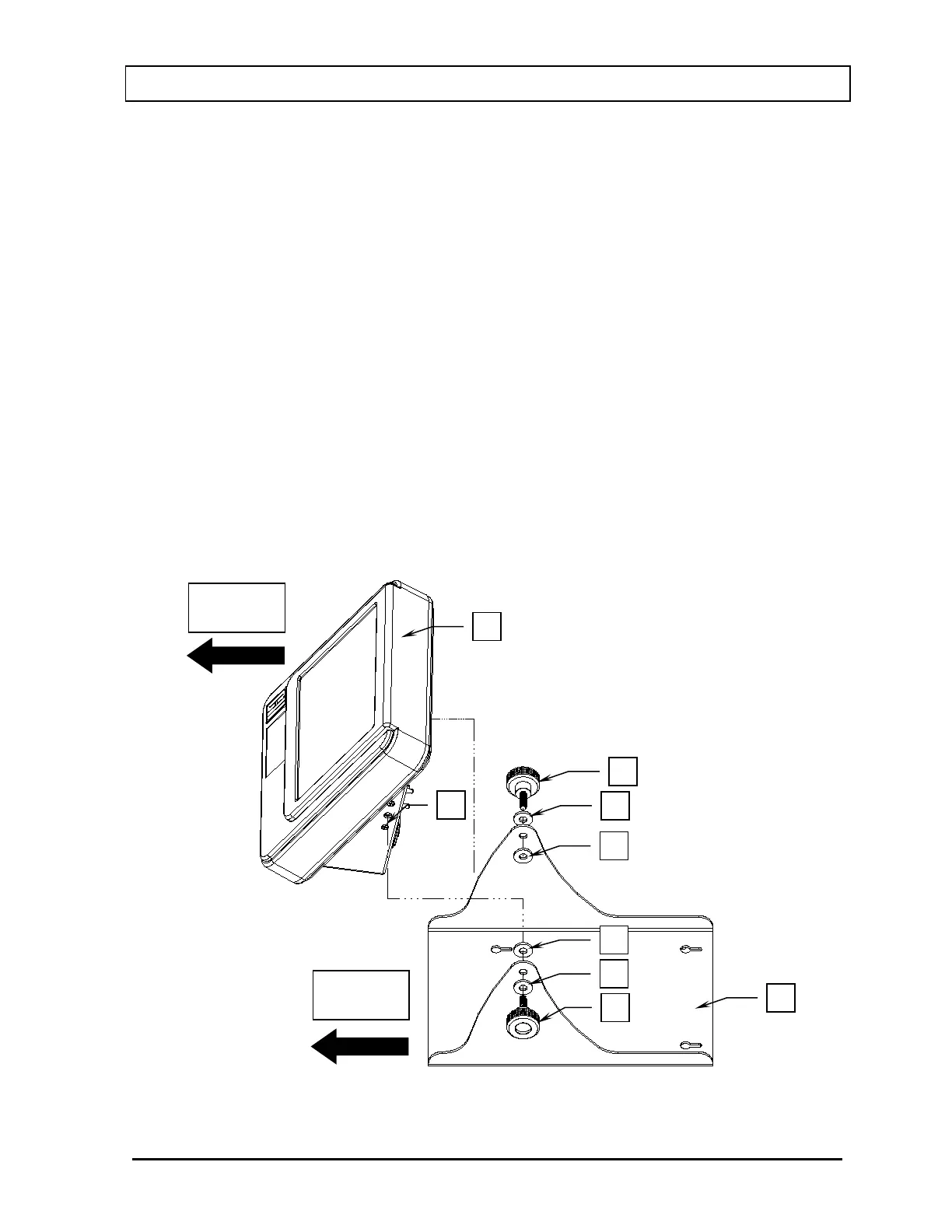
3. Slide washer (C) over the shaft of knob (D).
4. Insert knob (D) through one side of the Stand Base (B) and place another washer (E)
over the shaft of knob (D) (on the inside of the Stand Base).
5. With the front of Readout (A) facing the same direction as the front of Stand Base (B),
place the Readout onto the Stand Base.
6. Insert the shaft of knob (D) into mounting hole (F) located on the side of Readout (A).
Loosely tighten the knob.
7. Slide washer (G) over the shaft of knob (H).
8. Insert knob (H) through the other side of the Stand Base (B) and place another
washer (J) over the shaft of knob (H) (on the inside of the Stand Base).
9. Insert the shaft of knob (H) into the mounting hole located on the other side of
Readout (A). Note: The sides of the Stand Base (B) may need to be spread apart a
small amount to get the second knob to insert into the mounting hole.
10. Verify on each side that there is a washer located between the knob and the Stand
Base (on the outside of the Stand Base), and the Stand Base and the Readout (on
the inside of the Stand Base).
11. The knobs can now be fully tightened.
Figure 4-1 Readout/Stand Base Assembly